Effective substation grounding
At the beginning of my career in 2005, I had the opportunity to work at a 500kV substation with the National Transmission and Dispatch Company in Pakistan. During this time, I was introduced to various tools and techniques that were essential for maintaining the integrity of electrical infrastructure. One such tool was a primary injection test set, a device designed to inject large currents at low voltages, typically ranging from 50 to 2000 amps.

This test set was brought in to conduct a Grid Integrity Test, a process that involved injecting 100 amps of current into the earth and measuring the resulting voltages. At the time, this procedure seemed quite unusual to me, but it was crucial for assessing the health of the underground grid joints, which are vital for the overall reliability of the substation’s grounding system.
Later, I observed an earth resistance test being conducted at the same grid. This involved inserting two rods into the ground and measuring the earth resistance using the Fall-of-Potential method. This was a new concept to me, and it piqued my curiosity about the purpose and importance of such tests.
As I gained more experience, I came to understand that these tests are essential for ensuring the safety and effectiveness of substation grounding systems.
One of the fundamental components of an electrical substation is the grounding grid, which ensures the proper grounding of all apparatus in the substation, including transformers, circuit breakers, capacitor banks, and steel tower structures.
The grounding grid is strategically placed beneath the entire substation and serves a dual purpose: operational grounding and personnel safety. Operational grounding involves safely carrying fault currents into the earth without disrupting the operation of protective equipment. Personnel safety ensures that individuals in the vicinity are not exposed to dangerous electric shocks resulting from excessive step or touch potentials.
As simple as that! Let’s dive in details now!
- AC Primary Injection Testing: A Comprehensive Overview
- Understanding the Need for AC Primary Injection Testing
- Other Uses of Primary Injection Testing in Substations:
- Grid Integrity Test: Ensuring the Strength and Reliability of Earthing Systems:
- Grid Earth Resistance Testing:
- Fall-of-Potential Method for Earth Resistance Measurement: A Technical Overview
- BONUS (PDF) 🔗 Download Substation Earthing Guide
1. AC Primary Injection Testing: A Comprehensive Overview
In the realm of electrical testing, insulation resistance testing is widely known and routinely performed using high-voltage test devices, typically DC-based. These devices inject current into the insulation system to measure its resistance, providing valuable insights into the health of the insulation in terms of Ohms or Mega Ohms.
This testing is crucial for ensuring the integrity of electrical systems and preventing failures.
However, when it comes to assessing the health of electrical joints, a different approach is required — one that involves measuring joint resistance to evaluate their current-carrying capacity and overall reliability. This is where the AC Primary Injection Test Set comes into play.
2. Understanding the Need for AC Primary Injection Testing
While insulation resistance testing is effective for evaluating the insulation’s condition, it does not provide a complete picture when it comes to the current-carrying capacity of conductors or joints. Traditional resistance measurements, like those obtained using a multi-meter, involve injecting a small amount of current and measuring the resistance.
To thoroughly test a joint or connection, it is necessary to simulate real-world conditions by injecting a higher current, often close to the rated current of the system, for a specific duration (typically 30 to 60 seconds).
This approach not only measures the resistance but also assesses the joint’s ability to withstand the heat generated by the current, ensuring that the connection can handle operational conditions without degradation.
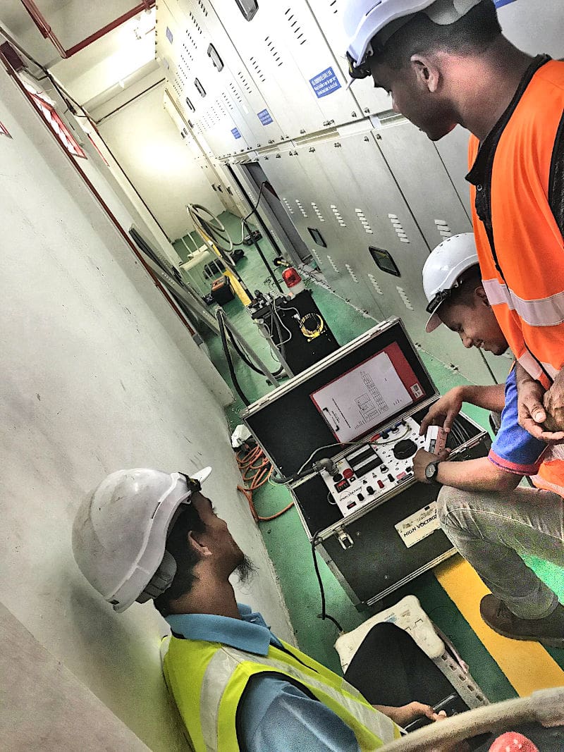
Figure 1 – Performing AC primary injection test on a switchgear


3. Other Uses of Primary Injection Testing in Substations
In addition to grid integrity testing, the primary injection test is a crucial procedure performed at substations to verify the accuracy of current transformers (CTs) and their associated circuits. Below, we will explore the various primary injection tests conducted for current transformers and their significance in ensuring the reliability of substation protection systems.
3.1 Stability Test
One of the key tests performed using an AC Primary Injection Test Set is the stability test for differential protection systems. During the commissioning of a substation, CTs may be incorrectly connected, with reversed polarities being a common mistake.
This error can cause an unintended differential current to flow through the relay, leading to the erroneous operation of differential protection and the tripping of circuit breakers under normal conditions – an outcome that is undesirable.
However, if the differential current equals the sum of the individual CT secondary currents, this indicates a polarity reversal. Corrective actions can then be taken to rectify the issue, ensuring that the protection system operates as intended.
Watch Video – Testing Primary Assets with OMICRON and the CPC 100
3.2 Identifying Loose Connections
Loose connections in electrical circuits can lead to significant safety hazards, including sparking and potential failures. The AC Primary Injection Test Set is invaluable for identifying such issues, provided the rated current is flowing through the connections during the test. When the test is conducted with a low current, sparking may not occur, masking the presence of loose connections.
Therefore, injecting a higher current during the primary injection test ensures that any loose connections are detected and corrected before they lead to operational problems.
3.3 Core Identification
In cases where a CT has multiple cores used for different purposes, core identification becomes essential. The AC Primary Injection Test Set facilitates this process by allowing technicians to short one of the cores at the CT terminal and observe that there is no current flow at the relevant load.
This verification process is repeated for each core, ensuring that the correct cores are identified and properly connected.


