
Estimated Study Time: 15 minutes
Substation level data acquisition
This technical article reviews substation level data acquisition architecture and communication protocol described in IEC 61850. IEC 61850 is the current international standard for substation automation (SA). The focus of IEC 61850 is to provide an interoperable standard for multivendor substation equipment to communicate.
 The story of IEC 61850 - A substation level data acquisition architecture and communication protocol (on photo: TransCo Laoag Substation at night; credit: MikeHansZach via Flickr)
To date, proprietary communication protocol has handcuffed the utilization of heterogeneous mix of substation equipment.
The description of IEC 61850 is a frame of reference from which three proposed substation level data acquisition architectures can be compared.
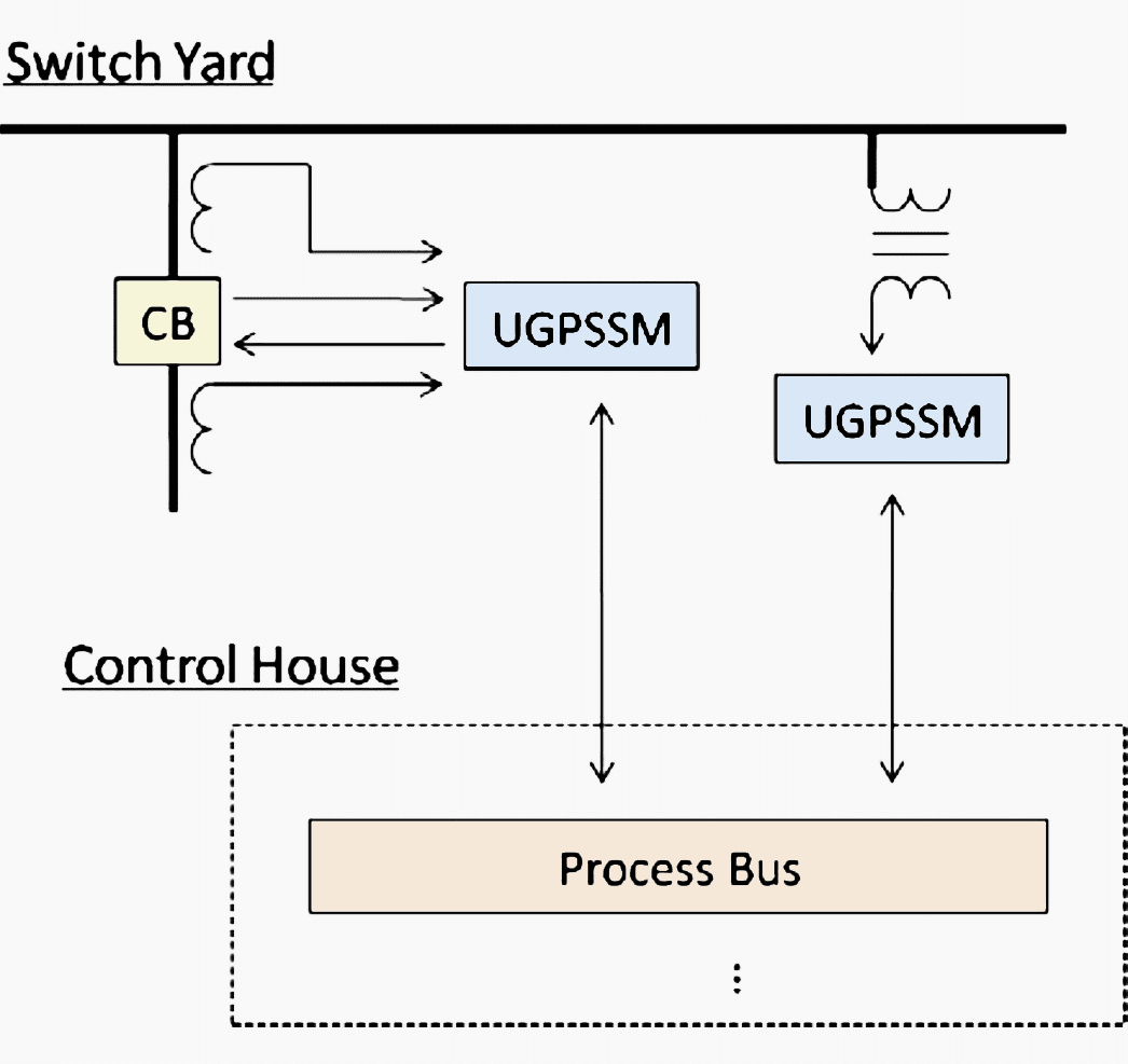
The substation level data acquisition system transmits data from the UGPSSMs (Universal GPS time-synchronized meters) to the control house. This functionality can be performed via multiple architectures.
Three such architectures will be described in terms of the flow of data in a typical substation. The three architectures described are: point to point, networked, and wireless. In the proposed substation of the future all collected data is initially processed via universal global positioning satellite (GPS) time-synchronized meter (UGPSSMs).
The UGPSSM device is similar to the IEC 61850 merging unit. The processing of each UGPSSM is to sample, digitize, and GPS time-stamp all substation data.
This article describes the functionality and proposed hardware of the UGPSSM.
1. IEC 61850 Substation Level Data Acquisition Overview
1.1 Data Flow
A conceptual diagram of the substation level data acquisition system outlined in the IEC standard 61850 “Communication Networks and Systems for Power Utility Automation” is shown in Figure 1a.
An example of technology, currently available, utilizing this approach is the GE HardFiber technology.

In Figure 2 the merging units (MUs) are analog to digital data collection devices which sample and digitize electrical quantities. The electrical quantities are analog or digital signals which are of interest.
Analog quantities include:
- Voltage and current signals from potential transformers (PTs) and current transformers (CTs),
- Transformer temperature signals from resistance temperature detectors (RTDs),
- Transformer turns ratios from potentiometers,
- etc.

Digital quantities include auxiliary contact outputs, etc. The MUs are placed physically close to the signals which they monitor. This arraignment minimizes the potential for signal corruption. Within the GE HardFiber system the MUs are called Bricks.
The GE Bricks include a weatherized exterior suitable for outdoor and extreme physical conditions common in substations.
Within the GE HardFiber system prefabricated fiber optic cabling is used between the Bricks and the termination points for the substation yard fiber optic cable the Cross Connect panels.

The Cross Connect panels are located within the substation control house (see Figure 3) and are used to connect Bricks to protection relays, meters, and any other intelligent electronic devices (IEDs).
The Cross Connect panels, as suggested by the name, allow fiber-optic cables to be patched between ports from the substation yard Bricks and control house IEDs.
The setup creates a dedicated fiber-optic communication channel between each Brick and corresponding IED.

In Figure 2 the process bus block represents the interconnection of MU data pathway to individual substation IEDs. The substation IEDs utilizes the digital data provided by the MUs to generate additional data.
Within the HardFiber system prefabricated fiber optic patch cords are utilized within the Cross Connect panels to create a continuous fiber optic channel between the Bricks and IEDs.
Thus, the station bus transmits data significantly slower than the process bus. This allows a networked architecture at the station bus.
In Figure 2 above the station bus facilitates data flow between all substation IEDs, substation control computers, and GATE hardware. This allows inter IED messaging, human machine interfacing, and communication with external stakeholders.
Key advantages of the HardFiber system include:
- Standardized optical fiber cabling;
- Prefabricated off the shelf components;
- Engineering, installation, commissioning, and operating utilized existing skill sets;
- GE UR-series relays and other 61850 compatible IEDs can be utilized; and
- Different IEDs can record sampled data at independent sampling rates.
IEC 61850 allows for legacy equipment to operate within the same substation with newer equipment. This is shown in Figure 2 where Relay A and PMU A monitor voltages and currents via analog instrumentation channels.
1.2 Communication Protocol
IEC 61850 is more than a typical communication protocol. IEC 61850 includes specifications on how to communicate data. It also specifies what data is to be communicated in an object orientated manner.
An overarching goal of the creators of IEC 61850 is to create a communication protocol which allows interoperable performance between all substation equipment vendors.
2. Substation Level Data Acquisition Architectures
Within all substations data is utilized locally and data is sent to external stakeholders. The architecture utilized to collect local data varies significantly from one substation to the next.
Three possible data collection architectures for the substation of the future are described next.
2.1 Point to Point
A conceptual design of the point to point architecture is shown in Figure 5.
In Figure 5 the UGPSSMs communicate via point to point fiber-optic or copper data link. Periodic data are provided from each UGPSSM.
Advantages of point to point communication includes: Highest speed throughput
Disadvantages of point to point communications includes:
- Demands the most raw material for the communication channels
- Demands the most infrastructure for communication right of way
A second method utilized to collect substation data is the networked architecture, described next.
2.2 Networked
A conceptual design of the networked architecture is shown in Figure 6.

In Figure 6 the output of each UGPSSM is routed via the router to the control house. The use of switched communication minimizes the amount of network link material.
Further, the switching communication increases the latency of the data flow.
The networked architecture has considerable market share of industrial and commercial communication infrastructure.
The use of networked communication infrastructure in substation environment is limited. The reliability and latency of this form of communication is questioned for the hard real-time systems utilized in power system automation.
Advantages of networked architecture includes:
- Lower requirement on communication channel material,
- Lower requirement on communication infrastructure.
Disadvantages of networked communications includes: Communication collisions cause delays.
A third method utilized to collect substation data is the networked architecture, described next.
2.3 Wireless
A conceptual view of the wireless architecture is shown in Figure 7.

The wireless architecture has similarities and differences from the last two substation level data acquisition architectures. To date wireless based substation level data acquisition methodology has not been utilized. Wireless based data transfer is utilized in other applications for power system operations and in many other technical areas.
In Figure 7 wireless modems are used to send the UGPSSM data to the control house.
Wireless communication requires only modems to be placed at each measurement location. Thus, limited infrastructure investment is required. The distances of typical substation data transmissions allow highly reliable point to point data transfers.
The use of wireless modems result in a measurable reliability concern that can be continuously monitored via the existence of transmitted data.
Advantages of wireless architecture includes:
- Lowest requirement on communication channel material,
- Lowest requirement on communication infrastructure.
Disadvantages of wireless communications includes:
- Cyber security concerns,
- Speed (this is not a disadvantage with new systems)
2.4 Communication Protocol
Multiple communication protocol exist which are applicable to substation level data acquisition.
A partial list of existing standards is provided below.
- DNP3
- MODBUS
- IEC 60890-5-103
- IEEE C37.118
- SEL Fast Message Protocol
The challenge of the substation of the future involves requiring high speed and reliability digital communications within the demanding environment of high voltage substations.
3. Substation Level Data Acquisition Architecture Overview
Of the three reviewed substation level data acquisition systems (point to point, networked, and wireless) the advantages of the wireless architecture are significant.
4. Universal GPS Time-Synchronized Meters
The UGPSSMs provide a common interface for all input and output data, between the switch yard equipment and the control house equipment, in the proposed substation automation structure.
A block diagram of the analog measurement channel within the proposed UGPSSM hardware is shown in Figure 8.
The digital measurement channels include optical isolation, microprocessor (µP), phase lock loop (PLL), and GPS clock signal. The control channels include optical isolation and µP only.

The blocks in Figure 8 provide the operation of the UGPSSM. Digitization (A/D) is provided by a 16 bit sigma/delta modulated analog to digital converter. GPS time-stamping is added to each measurement using a GPS clock signal. UGPSSMs also provide optical isolation between all low voltage hardware and the switchyard equipment.
In general, the UGPSSMs are placed physically close to the switch yard equipment which they monitor to minimize any low energy analog signal corruption.
The SuperCalibrator feedback signal in Figure 8 is utilized to automatically calibrate the measurement channels – leading to a self correcting measurement channel within the proposed substation automation structure.
By increasing the accuracy of the measurement channels results in higher accuracy local processing within the substation.
References //
- The Substation of the Future: A Feasibility Study (Final Project Report) by Power Systems Engineering Research Center
- GE Multilin HardFiber Process Bus System instruction manual
Related electrical guides & articles


Edvard Csanyi
Hi, I'm an electrical engineer, programmer and founder of EEP - Electrical Engineering Portal. I worked twelve years at Schneider Electric in the position of technical support for low- and medium-voltage projects and the design of busbar trunking systems.I'm highly specialized in the design of LV/MV switchgear and low-voltage, high-power busbar trunking (<6300A) in substations, commercial buildings and industry facilities. I'm also a professional in AutoCAD programming.
Profile: Edvard Csanyi

Excelent information,
Hi Edvard,
I am reading your articles since around ten years and they are very useful. I want to request you to write some article in IIOT also and believe that this is not the first time you have received such request.
Actually, I want to make carrier in this field and want to know more about this.
Thanks & Regards,
Anuj
UTILE ET VRAIMENT INTERESSANT
FELICITATIONS ET COURAGE