
Estimated Study Time: 18 minutes
Protection & switching configurations
The demand for power is growing rapidly due to increased industrial activities almost all across the world. Various generating sets of large ratings are being set up to meet this requirement. The generator, which is the source of power in networks, is a major component in electrical installations.
 HV/EHV substation switching configurations, control and protection functions
Equally important is the transmission system, which is used for distribution and the proper utilization of power generated by power plants. A fault or breakdown in the power plant or transmission network may have far-reaching consequences. It is therefore of paramount importance that the generators and transmission equipment are optimally used and efficiently protected.
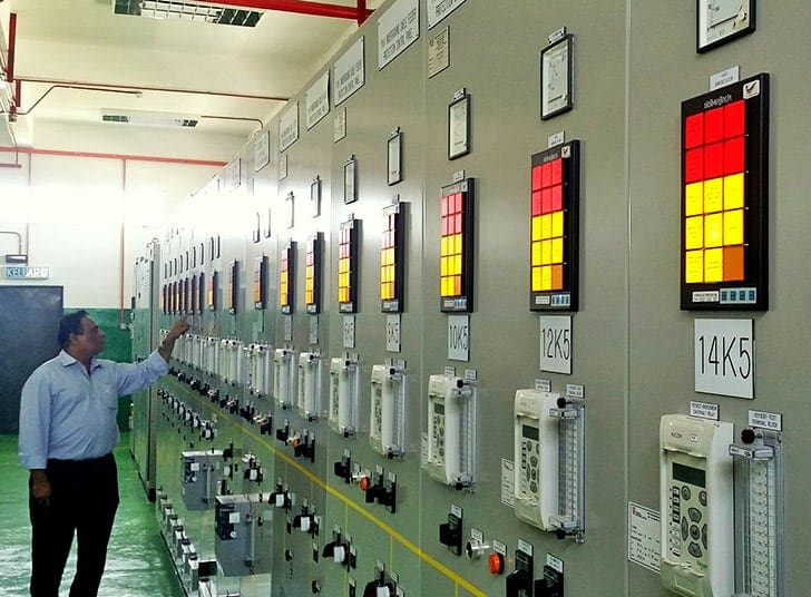
Then, there are control and protection panels, which are an integral part of HV and EHV transmission substations and switching stations. They have a functionally critical role.
Control and protection panels perform the following functions:
- They provide facility for centralized control.
- They provide a point for centralized supervision at which all vital information relating to controlled equipment is received and assimilated.
- They provide for necessary protection and isolation facility of all power circuits like generators, feeders, transformers, bus-coupler, reactors, etc.
- They provide alarm and trip commands under abnormal conditions and hence function like a watchdog for the system.
The manner in which the power apparatus is connected together in substations and switching stations, and the general layout of the power network, has a profound influence on protective relaying.
It is therefore necessary to review the alternatives, and the underlying reasons for selecting a particular configuration.
A radial system is a single-source arrangement with multiple loads, and is generally associated with a distribution system (defined as a system operating at voltages below 100 kV) or an industrial complex (Figure 2).
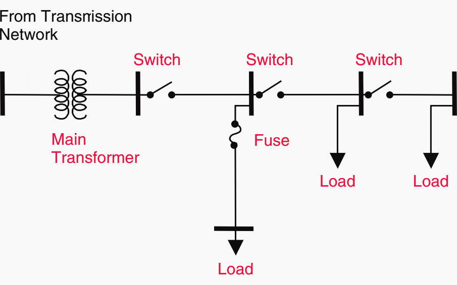
Such a system is most economical to build; but from the reliability point of view, the loss of the single source will result in the loss of service to all of the users. Opening main line reclosers or other sectionalizing devices for faults on the line sections will disconnect the loads downstream of the switching device.
A network has multiple sources and multiple loops between the sources and the loads. Subtransmission and transmission systems (generally defined as systems operating at voltages of 100–200 kV and above) are network systems.
See Figure 3.
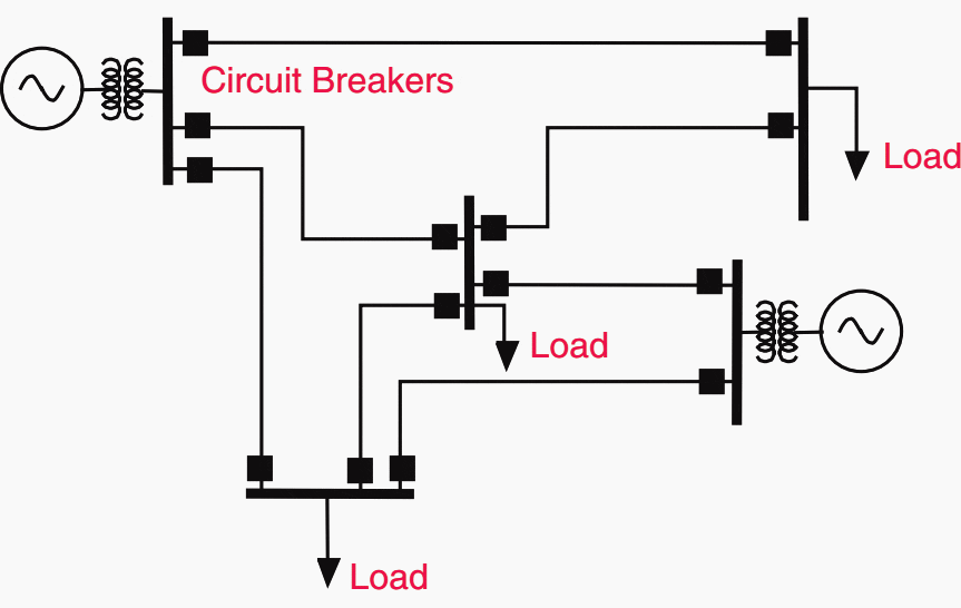
In a network, the number of lines and their interconnections provide more flexibility in maintaining service to customers, and the impact of the loss of a single generator or transmission line on service reliability is minimal.
Since sources of power exist on all sides of a fault, fault current contributions from each direction must be considered in designing the protection system. In addition, the magnitude of the fault current varies greatly with changes in system configuration and installed generation capacity.
Substation Design
Substations are designed for reliability of service and flexibility in operation, and to allow for equipment maintenance with a minimum interruption of service. The most common bus arrangements in a substation are:
- Single bus, single breaker,
- Two bus, single breaker,
- Two bus, two breakers,
- Ring bus and
- Breaker-and-a-half.
A single-bus, single-breaker arrangement, shown in Figure 4, is the simplest, and probably the least costly to build. However, it is also the least flexible. To do maintenance work on the bus, a breaker, or a disconnect switch, de-energizing the associated transmission lines is necessary.
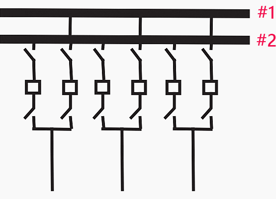
A two-bus, single-breaker arrangement, shown in Figure 5, allows the breakers to be maintained without de-energizing the associated line.
For system flexibility, and particularly to prevent a bus fault from splitting the system too drastically, some of the lines are connected to bus 1 and some to bus 2 (the transfer bus).
Note that the protective relaying associated with the buses and the line whose breaker is being maintained must also be reconnected to accommodate this new configuration.
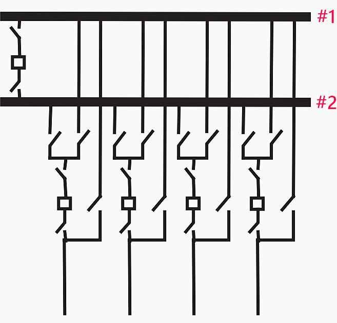
A two-bus, two-breaker arrangement is shown in Figure 6 below. This allows any bus or breaker to be removed from service, and the lines can be kept in service through the companion bus or breaker. A line fault requires two breakers to trip to clear a fault.
A bus fault must trip all of the breakers on the faulted bus, but does not affect the other bus or any of the lines. This station arrangement provides the greatest flexibility for system maintenance and operation.
However, this is at a considerable expense: the total number of breakers in a station equals twice the number of the lines.
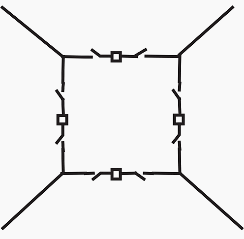
A ring bus arrangement shown in Figure 7 achieves similar flexibility while the ring is intact. When one breaker is being maintained, the ring is broken, and the remaining bus arrangement is no longer as flexible.
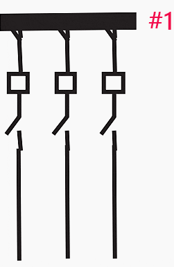
Finally, the breaker-and-a-half scheme, shown in Figure 8, is most commonly used in most extra high voltage (EHV) transmission substations. It provides for the same flexibility as the two-bus, two-breaker arrangement at the cost of just one-and-a-half breakers per line on an average.
This scheme also allows for future expansions in an orderly fashion.∗
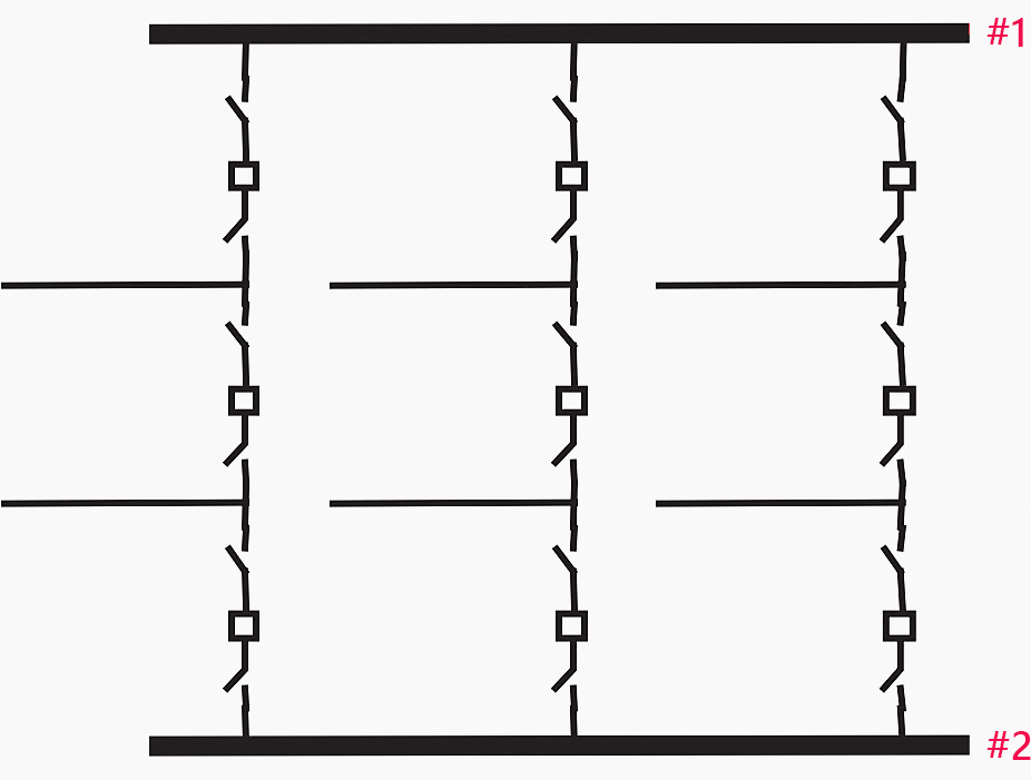
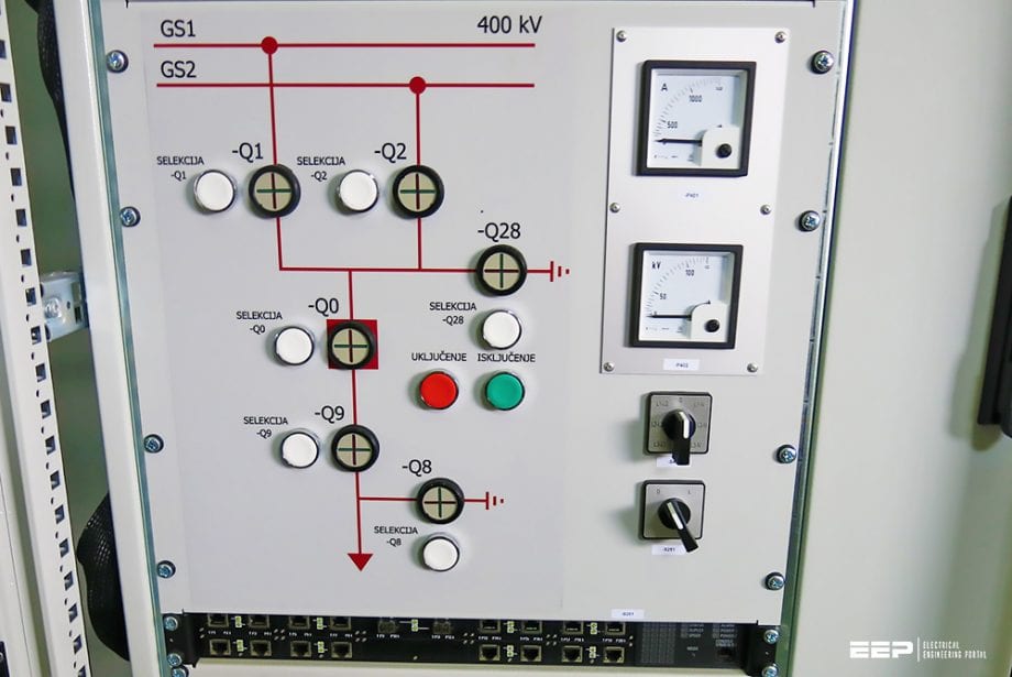
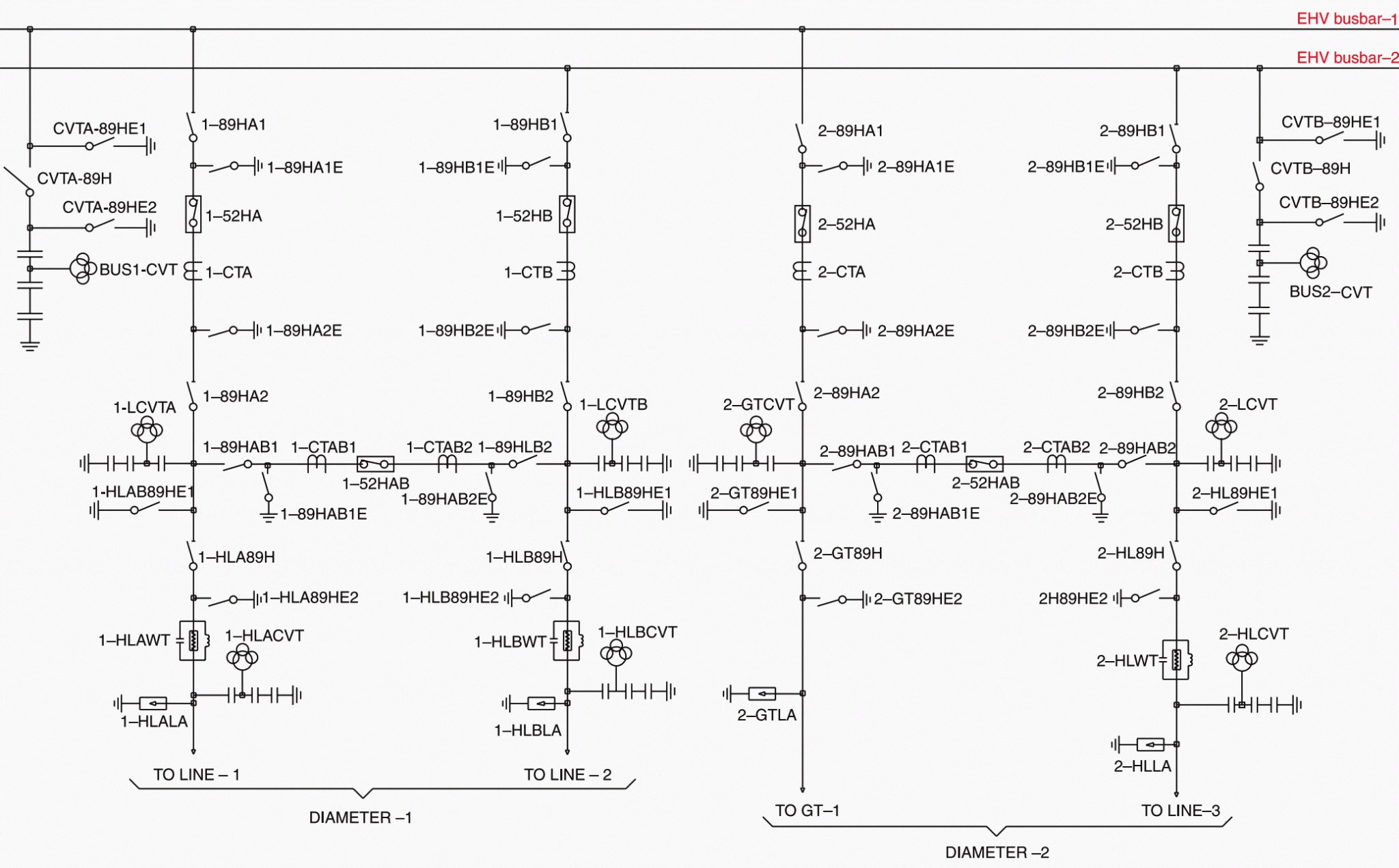
An arrangement of two circuits with the associated tie breaker is called a diameter. The diameter can be a line-line or line-transformer or transformer-transformer circuit diameter. Each diameter has three breakers for two circuits, hence the name one-and-a-half breaker system.
Normally all the three breakers are closed and power is fed to both the circuits from two buses which operate in parallel. The middle breaker or the tie breaker acts as a bus-coupler for the two circuits.
In case of failure of the breaker of any one circuit, the power is fed through the breaker of the second circuit and the tie breaker. Each breaker, therefore, has to have a rating suitable for feeding both the circuits.
A typical single line diagram of one-and-a-half breaker system is shown in Figure 1.
2. Control and Protection Functions
These include the following:
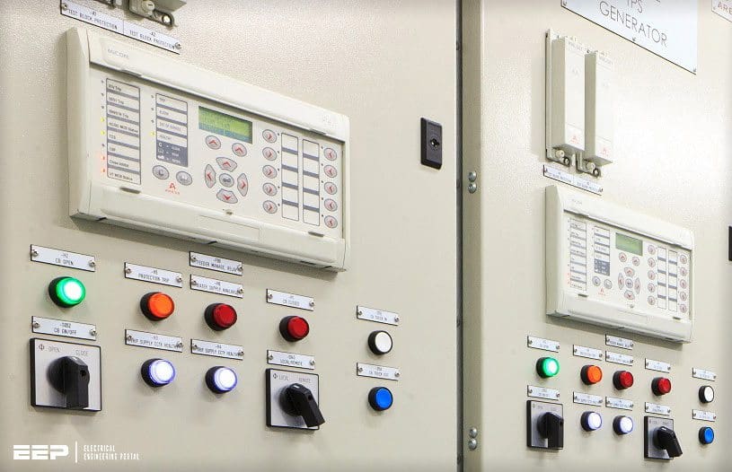
2.1 Control
This covers the ON/OFF functions using control/discrepancy switches for breakers and motor operated isolators. Suitable electrical interlocks are hardwired in the closing circuits of the breaker and isolators. The control is provided both locally and at remote as per the requirement.
2.2 Indication
ON/OFF indication is provided for breakers, isolators and earth switches using lamps or semaphore indicators. Auto-trip of circuit breakers and panel DC fail indications are also desired.
2.3 Protection
The function of protective relaying is to promptly remove from service any element of the power system that starts to operate in an abnormal manner. In general, relays do not prevent damage to equipment: they operate after some detectable damage has already occurred.
The control aspect of relaying systems also helps return the power system to an acceptable configuration as soon as possible so that service to customers can be restored.
2.4 Alarm Annunciation
Audio and visual alarms are provided to attract the attention of the operator in case of any fault. There are two types of fault alarms, viz. the trip alarms, which are due to serious faults causing tripping of the circuit breaker and the non-trip alarms due to faults, which are not so serious in nature and are annunciated to alert the operator to take corrective action before the trip condition arises.
The alarm condition is inscribed on the block window, which illuminates when the alarm occurs. Different colored blocks (red and amber) and/or different tones of audible devices are used to differentiate between the trip and non-trip alarms.
2.5 Metering
Electrical parameters like current, voltage, active power, reactive power, frequency, etc. are monitored for the convenience of the operator. For transmission lines, energy is monitored at high accuracy of the order of class 0.2 for the purpose of tariff metering.
Load profile data is also recorded for the purpose of analysis of energy flowing through the line.
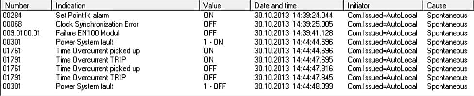
2.6 Event Logging
All fault conditions are time tagged with a real time clock and recorded as events on a printer for the purpose of fault analysis. Event recording can be provided as a built-in part of the numerical protection relays or by using a stand-alone event logger.
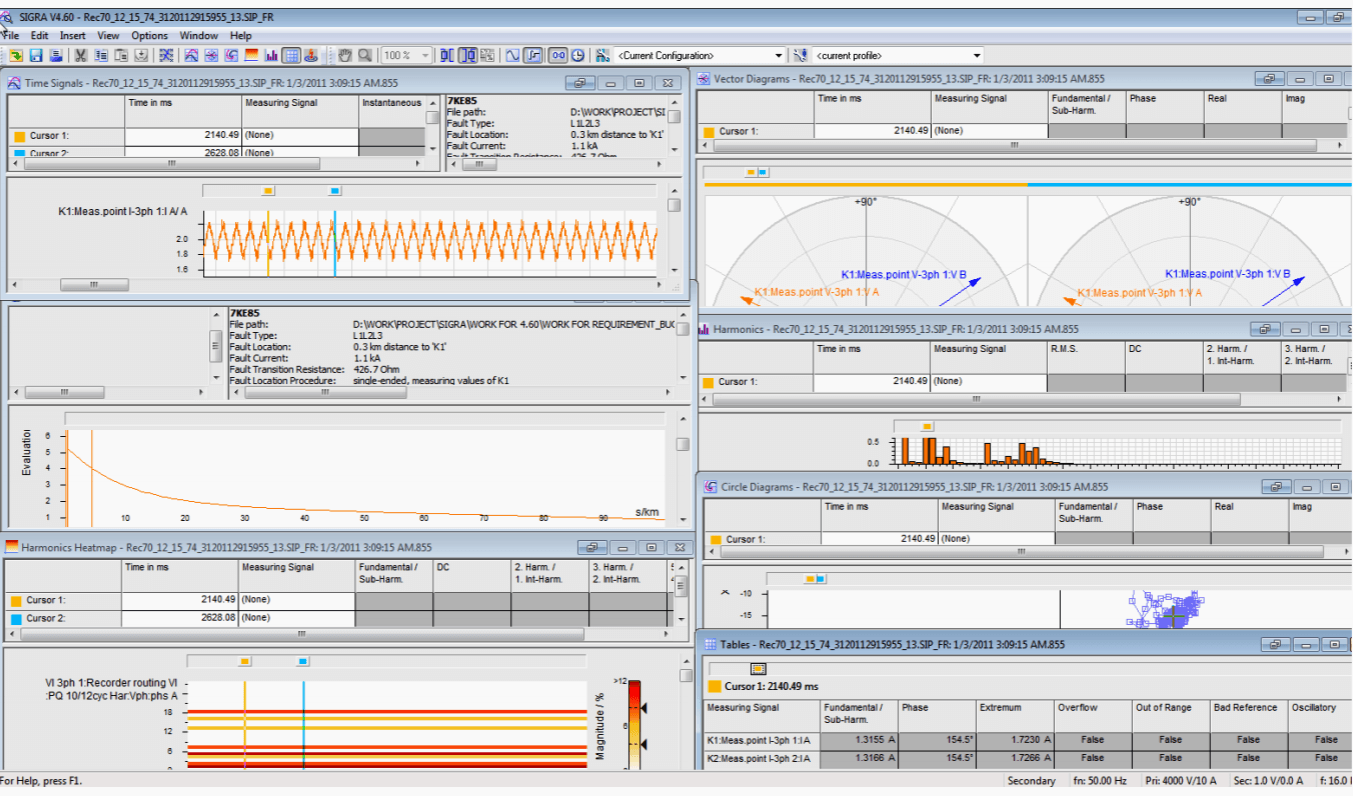
2.7 Disturbance Recording
It is a very important tool for the system analyst. On the occurrence of a fault in the system, the pre-fault, during fault and post-fault data are captured and recorded. The data includes current, voltage, selected internal logic signals, digital inputs and outputs.
The transient records are captured in the form of waveforms on a real time scale. These wave forms can be viewed on a personal computer using the disturbance analysis software.
Disturbance re-cording can be provided as a built-in part of the numerical protection relays or as a stand-alone disturbance recorder.
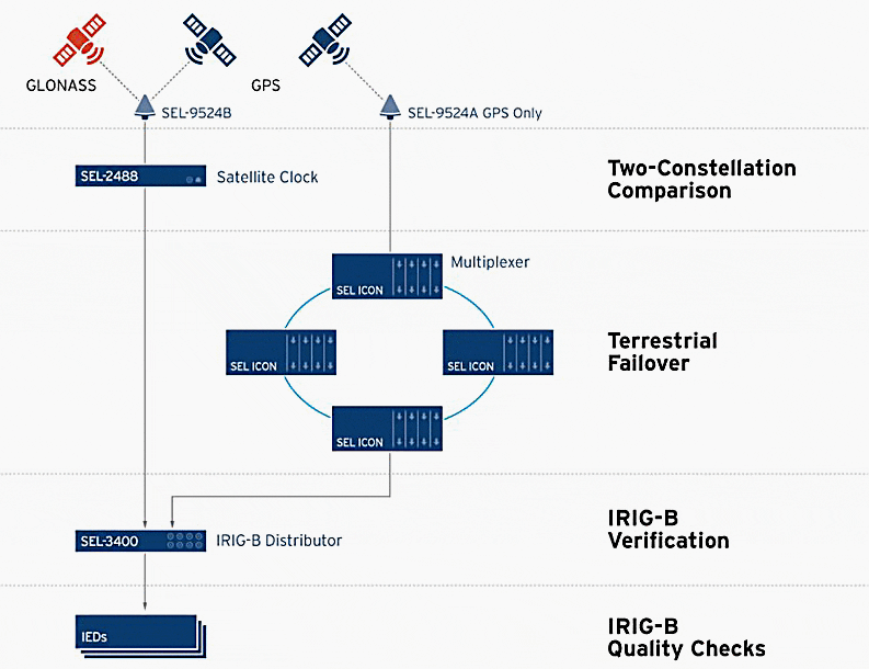
2.8 Time Synchronisation
Clocks of all devices like the event recorder, disturbance recorders, energy meters and numerical relays in a system should be synchronized with a common global position satellite (GPS) or GLONASS clock.
The GPS clock supplies the system with an accurate date and time, common to all locations wherever implemented.
tp]
2.9 Fault Location
This allows the operator to know the exact location of the fault on a transmission line. The distance to fault is indicated in kilometers or miles. Algorithm is written in the numerical distance protection relay or disturbance recorder software to calculate the distance to fault.
It is based on the reactance measurement principle.
2.10 Communication
Communication ports are provided for connection to a local PC and also for transmitting data to a remote integration system or supervisory control and data acquisition system (SCADA). A network interface device may be required between the numerical relay and SCADA.
The following functions are possible while communicating with the numerical relay:
- Retrieve settings from the relay
- Do necessary setting changes and upload them to the relay
- Retrieve/change/send programmable scheme logic to the relay
- Monitor electrical parameters and alarms
- Retrieve events, fault records
- Retrieve disturbance records from the relay for analysis, and
- Control breakers and other electrical devices.
2.11 Synchronizing
A circuit can be connected to grid only after proper synchronising. The circuit voltage, frequency and phase angle parameters are matched with the corresponding bus parameters before connecting to the grid. Synchronising is normally done using synchronising voltmeters, frequency meters, synchroscope and check synchronising relay.
The synchronising function is bypassed during dead circuit or dead bus condition.
2.12 Auto-reclosing
At times, the fault in a transmission line is of a transient nature. In view of this, when the breaker trips, it is normally closed immediately using the auto-recloser. In case of a transient fault, the circuit is restored after reclosing.
For single-phase faults, single pole tripping and high speed reclosing take place without check synchronising as the system remains in synchronism. In case of three-phase faults, reclosing is achieved through check synchronising.
Sources:
- Power system relaying by Stanley H. Horowitz and Arun G. Phadke
- Handbook of switchgears by Bharat Heavy Electricals Limited
- Event and Fault records in SIPROTEC COMPACT and SIPROTEC 4 relays by Siemens
- DIGSI 5 Software Description by Siemens
Related electrical guides & articles


Edvard Csanyi
Hi, I'm an electrical engineer, programmer and founder of EEP - Electrical Engineering Portal. I worked twelve years at Schneider Electric in the position of technical support for low- and medium-voltage projects and the design of busbar trunking systems.I'm highly specialized in the design of LV/MV switchgear and low-voltage, high-power busbar trunking (<6300A) in substations, commercial buildings and industry facilities. I'm also a professional in AutoCAD programming.
Profile: Edvard Csanyi

nice working
Good article for practising engineers.
Sir,
Earthing is a wide subject on electrical engineering. In case of pipe earthing electrode, what will be distance between two earthing to avoid any back flow of fault current. In case of neutral earthing, what will be size of the cable for neutral earthing. Presently we follow the 150 sq,mm multi strand,aluminium, armour single core cable. There is no specific guideline for such cable.
My opinion is
1) The size of the neutral cable of the main incomer shall be followed for DG set considering the same capacity of DG Set.
2) we follow the inter distance between two earth pits of twice of length of pipe electrodes.
We look forward the valuable comments with reference to the IS: 3043 and OISD -244.
Regards
Subrata Kumar Bera
Sir
I am associated your valuable input from your different excellent topic on electrical engineering.Please change my email ID from –
[email protected]
to
[email protected].
I shall be obliged.
With Warm regards
Subrata
9432012895
Hi Sir
Could you please let know the best software for electrical design, analysis and simulation of T&D networks
Good writing for electric
I am electrical engineer how can more learn electrical knowledge
Hi Sir,
Thanks a lot for sharing your useful knowledge.it really an eye opener to me to widen electrical knowledge.
Hi Sir,
Hi Sir
very useful and highly valuable information to all dealing with electrical works. Sometimes it is not easy to get information like this to people like me.Thank You so much.
Design analysis of optimization of Low Voltage Distribution System (LVDS) into High Voltage Distribution System (HVDS) in Nigeria’s power system