
Transformer alarms
Transformers are the most expensive piece of apparatus in a power substation and therefore must have appropriate protection equipment installed to guard against various faults. This technical article explains a few internal transformer faults that make an alarm in a substation. For substation crew it’s always important to understand what is going on inside a transformer and why.
 5 alarms coming from a substation transformer you MUST pay attention to
In order to react properly in faulty situations it’s important for operator to understand how internal protection mechanisms of a transformer work. For example, switching operators must not energize any substation transformer that has tripped off on fault.
When confronted with this situation the substation operators must:
- Check all associated relay panels and log protection flags
- Visually inspect the transformer
- Contact in-charge person from control center and inform of exact details of the fault.
Together with the usual type of protection relays (i.e. overcurrent, earth fault) used elsewhere on the system, transformers have additional protection.
These include alarms and trips that guard against:
- Low oil level alarm
- Gas build up and oil surge (Buchholz trip)
- Winding temperature (overheating)
- Oil temperature (overheating)
- Malfunction of an earthing compensator (differential/restricted earth fault)
- Over-excitation
Important to note!
Unless approval is given by the relevant in-charge person from a substation control center, a switching operator must never attempt to put a substation transformer which has tripped on protection back into service, because of the risk that energizing the transformer could do further damage.
1. Low Oil Level Alarm
Some substation transformers have an inbuilt alarm on the conservator tank level gauge (see Figure 1). If the oil level falls below a preset level an alarm will be triggered. These alarms are usually relayed to the control center.
Two types of oil level indicators are shown on Figure 1 below.
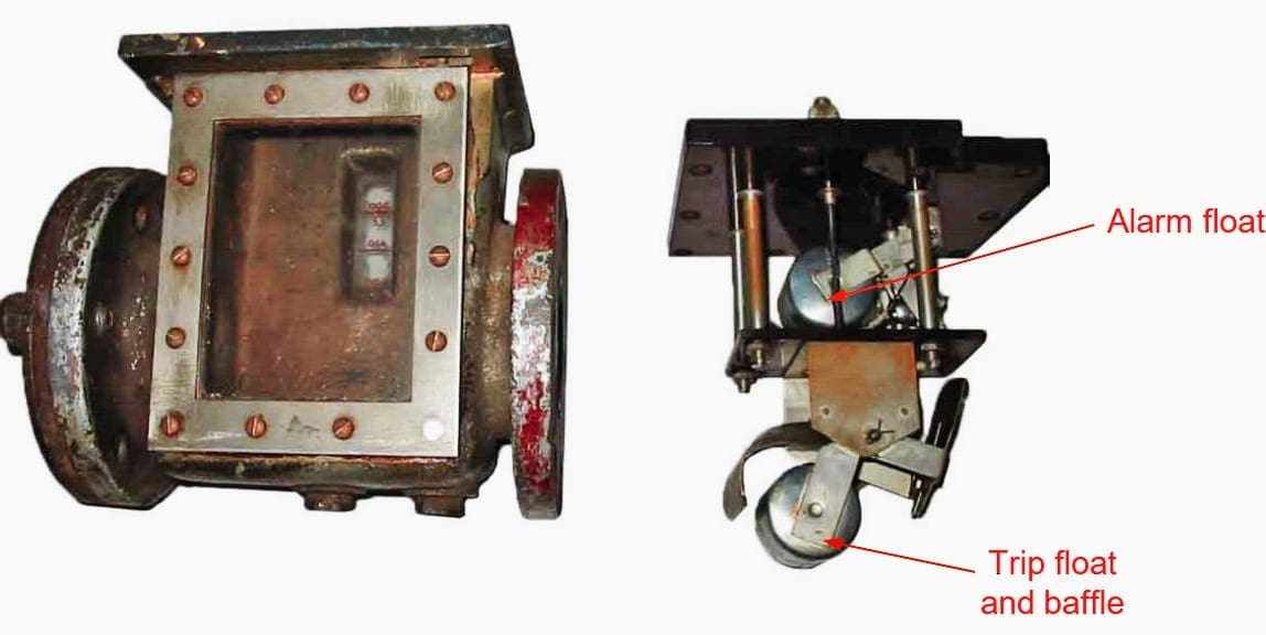
Type 2 is simply an oil level gauge. If no low oil alarm is available on the conservator, a Buchholz gas alarm will also indicate if the oil level is low. This is due to the float arrangement inside the transformer Buchholz relay activating either for a build-up of gas from inside the transformer, or from the oil level reduction in the relay housing.

If flagging indicates a low oil level, investigations must be carried out to find if the problem is sufficient to warrant de-energization of the transformer until the oil level can be increased. If the flags indicate ‘Buchholz gas alarm’ the transformer must be taken out of service as soon as possible and investigations made to find if the cause of the alarm was minimum oil level or gas build up from inside the tank.
Gas in the Buchholz relay should always be removed for analysis.
2. Buchholz Trip
The most important function of the Buchholz is to trip the transformer when:
- Internal fault causes a surge of gas or oil from inside the transformer, or
- The main oil level of the transformer drops below the Buchholz relay.
These points are important because the quicker these faults can be removed, the least amount of damage will result inside the transformer.
For any Buchholz trip alarm, the appropriate technical staff must be brought in to take samples of gas or oil via the Buchholz bleeder valves for chemical analysis. This analysis gives positive indication on the exact type of fault and its extent. Decisions can then be made about the transformers future.
Note that some transformers have an additional Buchholz pressure-activated relay fitted for the tap changer tank.
3. Winding Temperature
The winding temperature indicator is to:
- Start auxiliary cooling fans and/or oil pumps
- Activate an over-temperature alarm, and
- Initiate a trip of the transformer circuit breakers if the temperature continues to rise
For example, a 20/27MVA transformer will run at 20MVA without any cooling equipment, but at 27MVA with all cooling equipment running.
If a winding temperature alarm is activated it is normally due to either:
- An overload of the transformer causing heat increase, or
- Malfunction of cooling equipment causing a heat increase in the transformer.
Inspection of the transformer and its loading will dictate what action needs to be taken. The winding temperature circuit is connected so that extra cooling facilities (fans/pumps) are activated before the alarm/trip function.
See Figure 3 above.
Important Notes!
The temperature values as shown in Figure 3 are typical values and may vary on different transformers. Care should be taken when testing cooling fans and pumps to ensure that the control circuits are restored to normal operation after testing is complete.
4. Oil Temperature
This protection has two main purposes:
- To initiate an oil over-temperature alarm, and
- To initiate oil over-temperature tripping of the transformer circuit breakers.
The alarm and trip settings on this protection are set lower than the winding temperature gauge. This is due to the fact that the heat generated by the windings is dissipated through the cooling medium (oil) and so the alarm setting on the oil gauge (95° C) roughly corresponds to the alarm setting on the winding gauge (120° C) (see Figure 3).
Oil and winding protection can be used singularly or both together, they are used for the same purpose. One acts as a backup for the other, ensuring efficient protection of the transformer. Where a transformer is not fitted with pumps and fans, usually only an oil temperature alarm is fitted.
As mentioned previously, an alarm or trip on either oil or winding temperature protection, must be viewed seriously.
Where a transformer trips on winding or oil temperature the transformer should not be re-energized until approval is given by the relevant person in substation control center.
5. Malfunction of an Earthing Compensator
An earthing compensator transformer is used on power transformers with a delta secondary supplying feeders or a delta tertiary winding which supplies reactors or station supply transformers (See Figure 4 below).
The earthing compensator provides an earth reference on the delta winding, facilitating the detection of earth faults on connected apparatus.

Earthing compensator transformers are used:
- To allow a return path for earth currents in the event of faults on the circuits connected to the winding
- To reduce fault current level
- To allow measurement of earth currents for various types of transformer protection, and
- To limit the rise in voltage on the sound phases in the event of a fault.
The earthing compensator transformer is an integral part of the operation of the main transformer. If it becomes defective or for some reason malfunctions, the main transformer must also be taken out of service.
6. Over-Excitation of Transformers
Transformers are designed for operation over a range of voltages which ensure that the core is not over excited. Over-excitation of the core, due to operation at higher than design voltages, causes magnetic saturation of the core leading to overheating and possible damage to the core.
Transformers should always be operated within the normal design range of voltages.
The magnetic flux in the core is proportional to the voltage applied to the winding divided by the impedance of the winding. The flux in the core increases with either increasing voltage or decreasing frequency.
During startup or shutdown of generator-connected transformers, or following a load rejection, the transformer may experience an excessive ratio of volts to hertz, that is, become overexcited.
When a transformer core is overexcited, the core is operating in a non-linear magnetic region, and creates harmonic components in the exciting current. A significant amount of current at the 5th harmonic is characteristic of overexcitation.
Sources:
- Switching Operator’s Manual – Transmission Switching by Horizon Power
- Transformer Protection Principles – General Electric


Thanks so much for the write-up, very educative and motivative.
Very good paper. Thanks.
so useful
Very useful and informative. Thank you.
Dear Sir Edvard
Your post are very useful and helping us to improve our knowledge. Nevertheless, could you give some information about non oil transformer.. with air insulation.
Kind Regards.
m.Changala
What Is BAU transformer fault
Very helpful for engineers, thank You for the clear and simple explanation
You’re welcome Hendarman!
Very useful…good job
Very Brief and quite informative, Keep it up.
Nice one engr i real enjoyed your article on power transformer protection. My question is what is the reason /causes of low oil level in a power transformer when the transformer is not have oil leakage issues
As I only looked for couple minutes i saw lot of things as can be updated as to more aficionados as to what we have today special the turbines as how the fans getting to hot as a new design will helped with the flowing and safety of well being as well more productive as well long lasting and you may consider as to use nitrogen as a cool substitute as to run much more oficion and productive as well lot more lasting and safety features as to run hot and melting water entire I understand how nitrogen works as 100 below zero as I have used it many years as racing aplication with turbos and natural aspirated as to have its balance is no harm and it’s used to cool off the charger if I was your ungenerous I would think really about it as will make it do much productive and will safe in the long run so much money and produce much more as costs as well.
Very usefull paper. One question; is it possible in terms of the alarming functions to get a digital or analog output?
Thanks this message will useful for engineers
It will very helpful for everone
Very educative and easy to understand thanks
This is substation operations made easy. The transformer must always be protected from damage. Thanks for sharing
Thanks for sharing very important informations.
Your article is more educative than what we learnt in school. May God bless you sir.
very useful & important information for substation operator.if you communicate information ,then that is easy to prevent accident.
Wow I’m interested in your letter it will help me gain more experience in the power sector
Wow I’m interested in your letter
Dear Edvard,
Thanks for useful article. It’s practically and noticeable. Moreover some comments come down. Please check them and let us to clarify;
– The important alarms before tripping is more vital to attention. For example, it is recommended to have cooling started alarm when fans are started to make a sense of acknowledgement by network operators. To control load and monitor the Transformer. Since of experience visual check and inspection is so vital to do every two hours. Because oil leakage generally happened slowly by absorbing dust and making oily body of transformer. It’s not happening suddenly rarely.
– Winding temperature is more important because of live parts and the trigger of fans is winding temperature. As you know the stop is oil temperature for fans. So use of Transformer Monitoring Management System ( TMMS ) can be useful to reduce risk of operation and keep stability of Transformer.
Good information and helpful
Good and helpful article
Informative…
Thx
Sir,what is the use of using alarms in transformers
Great alarm notifications on the main part of HV substations. Tap changer alarms are worth to be mentioned.
Thanks for this great article. Very useful information.
Thanks for the information, as I had worked in 900 Mw hydroelectric generating station for more than 25 years, it has helped me to remember
my experience.
This page is educative
It’s will be helpfull for engineers
A complete session of full technically exposure 👍
Good
Very nice article, used for SCADA signal preparing for Transformers, also I have one query is this signals gets varry depending on kV ? Please update. Thanks overall article is very good and knowledgeable.