Troubleshooting transformers
Let us remind ourselves of the basics of substation transformer parts, their operation principles, and do’s and don’ts for safety measures and precautions. For novice substation engineers it’s important to recognize every single detail of a transformer and later to learn to perform various troubleshooting.
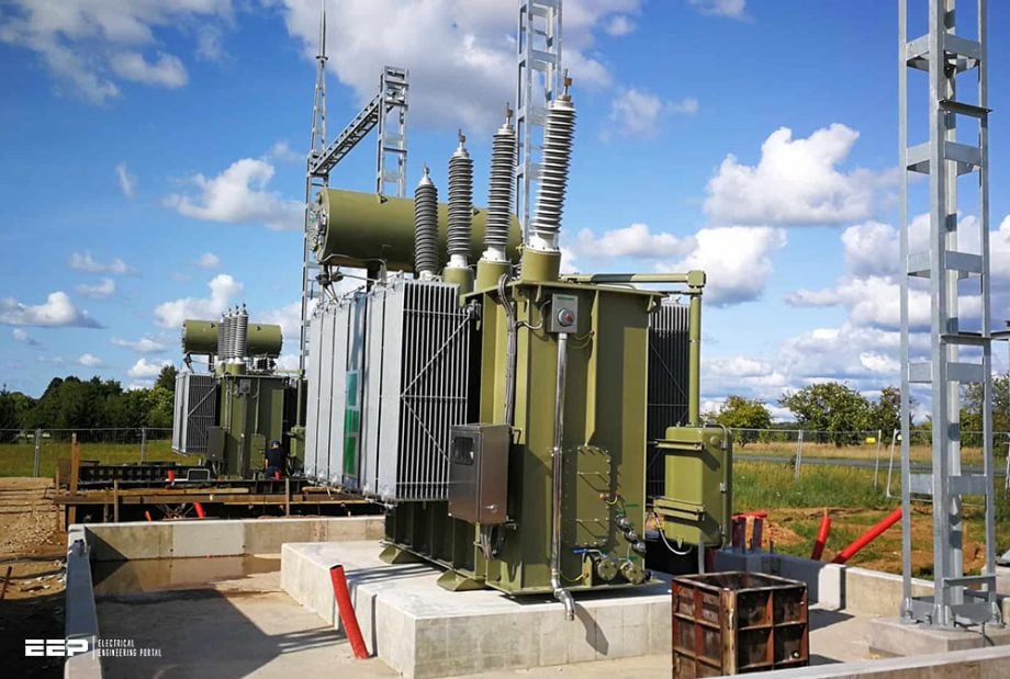
The substation transformer is static equipment, which converts electrical energy from one voltage to another. As the system voltage goes up, the techniques to be used for the design, construction, installation, operation, and maintenance also become more and more critical.
It is very essential that the personnel associated with the installation, operation, or maintenance of the transformer are thorough with the instructions provided by the manufacturer.
This technical article contains general descriptions of substation transformer parts (mainly up to 50kV) and some specific details about some of the parts that are important in terms of safety and maintenance. All this is essential for the safety aspects, erection, commissioning, operation, maintenance, and troubleshooting of substation power transformers.
1. Transformer Construction
The techniques used in the design and construction of high voltage transformers vary from manufacturer to manufacturer. The active parts of the transformers consist of core and windings.
1.1 The Core
The core is manufactured from a lamination of Cold Rolled Grain Oriented Silicon Steel, which gives very low specific loss at operating flux densities. Joints of the laminations are designed such that the electromagnetic flux is always in the direction of grain orientation.
The core clamping structure is designed such that it takes care of all the forces produced in the windings in the event of any short circuit.
Figure 1 – Transformer core and coils assembly


Go back to the Contents Table ↑
1.2 Windings
Windings are made from paper insulated copper conductors which are transposed at regular intervals throughout the winding for ensuring equal flux linkage and current distribution between strands.
Interleaved or shielded construction is adopted for the high voltage windings to ensure uniform distribution of impulse voltages. Insulation spacers in the winding are arranged such that oil is directed through the entire windings for ensuring proper cooling.
Go back to the Contents Table ↑
1.3 Cooling
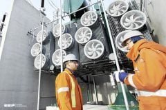
For ONAN/ONAF cooling, oil flows through the winding and external cooler unit attached to the tank by the thermosyphon effect. For OF AF/OD AF/ OF WF cooling, the oil is directed through the winding by oil pumps provided in the external cooler unit.
External cooler unit/units consist of pressed steel sheet radiators mounted directly on the tank or separate cooler banks for air-cooled transformers and oil to water heat exchangers for water-cooled transformers.
Figure 2 – Transformer cooling fans


Go back to the Contents Table ↑
1.4 Tank and Cover
Tank and Cover are manufactured by welding steel plates and are suitable for withstanding full vacuum and positive pressure tests. For large capacity power transformers, the tank will be of bell-type construction. This is to avoid lifting heavy core and windings, which requires a very large capacity crane at the site. The weight of the upper tank will be much less in comparison with that of core and windings and can be lifted by using a small capacity crane.
Note that the transformer tank is provided with two earthing terminals. While earthing the cable box, bus duct, etc., it should be ensured that no closed loop is formed because of multiple earthing connections.
Figure 3 – Transformer tank and cover


Go back to the Contents Table ↑
1.5 Conservator
A conservator is provided to take care of the expansion and contraction of transformer oil, which takes place during the normal operation of the transformer. Wherever specified flexible separators or air cell if provided in the conservator can prevent direct contact of air with the transformer oil. A smaller oil expansion vessel is provided for the On-Load Tap Changer.
A magnetic oil level gauge is fitted on the main conservator which can give alarm/trip in the event of the oil level falling below the pre-set levels due to any reason.
Figure 4 – Conservator and its oil level indicator


Go back to the Contents Table ↑
1.6 Pressure Relief Device
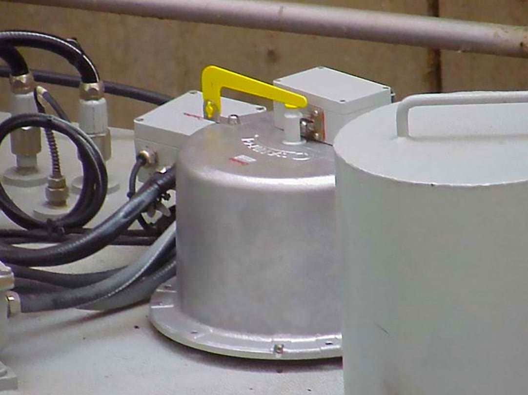
A device for avoiding high oil pressure build-up inside the transformer during fault conditions is fitted on top of the tank. The pressure relief device allows rapid release of excessive pressure that may be generated in the event of a serious fault. This device is fitted with an alarm/trip switch.
The pressure relief device has a spring-loaded diaphragm, which provides rapid amplification of its actuating force and will reset automatically, as soon as the pressure inside the tank drops down to the pre-set pressure.
The relief device is provided with a shielded weatherproof alarm/trip and is operated by the movement of the valve disc.
For Small Capacity transformers, an explosion vent is provided with a diaphragm, which will break in the event of an abnormal increase in internal pressure. Sometimes the explosion vent is provided with a double diaphragm such that the outer one remains intact even after the inner one is ruptured.
Rupturing of the inside diaphragm can be checked by viewing through the oil level gauge provided in between the diaphragms.
Figure 5 – Pressure relief device installed on top of the transformer

Go back to the Contents Table ↑
1.7 Gas & Oil Actuated (Buchholz) Relay
Gas and oil actuated relay is fitted in the feed pipe from the transformer tank to the expansion vessel for collection of gas if generated in the oil. The relay operates on the fact that almost every type of fault in an oil-immersed transformer gives rise to a generation of gas.
This gas is collected in the body of the relay and is used to close the alarm switch.
It works the following way: Two brass petcocks are fitted at the top of the relay body, the outlets of which are threaded to take a bleed pipe if required for the collection of gas samples. In the pipe connection between On Load Tap Changer and its oil expansion vessel, a single float Oil Surge Relay is fitted.
This relay operates on the principle of oil surge impinging on a flap causing operation of the mercury switch connected to the trip circuit. The gas-actuated alarm switch is eliminated because the gas generated during normal tap changing operation will give the unnecessary alarm.
Suggested Reading – Troubleshooting Buchholz relay and recommended actions
Troubleshooting Buchholz relay and recommended actions when it operates
Go back to the Contents Table ↑
1.8 Silicagel Breather
Expansion and contraction of oil cause breathing action. The silica gel dehydrating breather absorbs any humidity in the air breathed. An oil seal in the air intake prevents external moisture from being absorbed when no breathing occurs.
The breather container is filled with silica gel crystals. It is arranged such that the air breathed must pass through it. The desiccant contains blue and white crystals. When the silica gel is fully active, the blue crystals will have a deep blue color and change to pink as it absorbs moisture. When saturated with moisture, the silica gel contained should be replaced. The gel removed from the breather may be arranged for regeneration and preserved for future use.
The silica gel crystals are bright orange in the case of a non-carcinogenic silica gel breather and turn purple/bluish when exposed to moisture.
The loading pattern and the site conditions are difficult for the transformer manufacturer to assess. Hence, the selection of the breather is based on certain assumptions and it is difficult to fix up a time schedule for the regeneration of silica gel. It is advisable to have a periodic inspection (say monthly) of the indicator so that the gel can be regenerated or replaced as soon it is saturated with moisture.
It’s important to fill the oil in the oil cup up to the marked level on it.
Figure 6 – Transformer silica gel dehydrating breather


Go back to the Contents Table ↑
1.9 Winding Temperature Indicator
The winding temperature relay indicates the winding temperature of the transformer and operates the alarm, trip, and cooler control contacts. This instrument operates on the principle of thermal imaging and it is not an actual measurement.
The instrument is provided with a maximum temperature indicator. The heating resistance is fed by a current transformer associated with the loaded winding of the transformer. (The heating resistance is made from the same material as that of the winding) The increase in the temperature of the resistance is proportionate to that of the winding.
The sensor bulb of the instrument is in the hottest oil of the transformer; therefore, the winding temperature indicates a temperature of hottest oil plus the winding temperature rise above hot oil i.e. the hot spot temperature.
Figure 7 – Transformer winding temperature indicator


Go back to the Contents Table ↑
1.10 Oil Temperature Indicator
The oil temperature indicator consists of a sensor bulb, capillary tube, and a dial thermometer. The sensor bulb is fitted at the location of the hottest oil. The sensor bulb and capillary tube are fitted with an evaporation liquid.
The vapor pressure varies with temperature and is transmitted to a bourdon tube inside the dial thermometer, which moves in accordance with the changes in pressure, which is proportional to the temperature.
Figure 8 – Both winding temperature and oil temperature indicators installed side by side


Go back to the Contents Table ↑
1.11 Bushings
The high voltage connections pass from the windings to terminal bushings. Terminal bushings up to 36 kV class, 3150 Amps, are normally of plain porcelain and oil communicating type. Higher current rated bushings and bushings of 52 kV class and above will be of oil-impregnated paper condenser type.
The oil inside the condenser bushings must not be communicating with the oil inside the transformer. Oil level gauge is provided on the expansion chambers of the condenser bushings.
Oil in the condenser bushing is hermetically sealed and should not be disturbed in normal operation. The oil level may be checked regularly and any oil leakage should be reported to the bushing manufacturer for immediate attention.
Figure 9 – Transformer bushings being tested


Go back to the Contents Table ↑
1.12 Tap Changer
Tap changers of power transformers are specifically of two types. On-Load Tap changer ii. Off Circuit Tap changer. In the case of off circuit tap changer, the tap changing takes place only when the transformer is de-energized, but in the case of on-load tap changers, the tap changing takes place when the transformer is in operation.
The tap changer can be designed for changing the taps:
- Manually
- Automatically, and
- Remotely.
The Selector switch contacts should be examined after every 10,000 operations and replaced when burning of the copper tungsten tips and blocks have progressed to the copper base.
Oil samples should be taken and checked after every 5000 operations or 6 months whichever is earlier for electrical breakdown. If the samples fail consistently below 30kV for 1min in a standard test cell, the oil should be changed. During an oil change, the selector switch should be clean down to remove adhering carbon.
The tank should be cleaned out and filled with fresh oil having a test value of 60kV minimum to the level indicated on the sight gauge.
Figure 10 – Maintenance of on-load tap-changer


Go back to the Contents Table ↑
1.13 Control and Monitoring System
Local control and monitoring of the cooler, tap changer, and alarm/trip indicators are carried out at the marshaling kiosk. Automatic control of the tap changer is carried out at the remote control panel.
Suggested reading – My worst experience in the maintenance & supervision of MV substations
My worst experience in the maintenance and supervision of medium voltage substations
Go back to the Contents Table ↑
1.14 Fire Detection & Fire Fighting System
It is recommended to always install suitable fire detection and fighting system with all transformers. CBIP Manual prescribes guidelines for the selection and installation of the Fire Protection System.
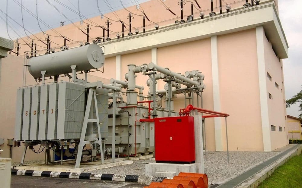
“Automatic Mulsifyre System” or “Drain and Stir System” with nitrogen injection inside the transformer are more prominent among the firefighting systems for large capacity Power Transformers. In the Drain and Stir System, oil is partially drained from the transformer, and nitrogen gas is bubbled through the oil in the transformer tank to stir and create a blanket of inert gas above the oil to quench the fire.
The owner of the Transformer must ensure the provision of requisite Contacts/Relays in his control panel as per the requirement specified in the Fire System Instruction Manual for connecting the Fire Detection and firefighting System.
Figure 11 – Transformer fire protection system with nitrogen

Go back to the Contents Table ↑
2. Do’s And Don’ts For Safety Measures / Precautions
2.1 Do’s
- Insulating oil and insulation of windings and connections are inflammable. Watch for fire hazards.
- Before entering inside the Transformer, replace Nitrogen gas completely with air if it was transported with nitrogen gas inside.
- Make sure that nothing is kept inside the pockets before one enters the main unit. Also, take off the wristwatches and shoes.
- List up all the tools and materials to be taken inside and check them after coming out to make sure that no tools are left inside.
- There must be a protective guard for the lamp to be taken inside.
- Keep inspection covers open for supply of fresh air when someone is working inside.
- When one person is working inside, the second person must be available outside for emergency help.
- Use rings spanners and tie them to the wrist of the person or somewhere outside the tank.
- Be careful during connections where bolted joints are involved so that nuts, washers, etc. are not dropped inside the tank.
- De-energize the unit with circuit breakers and line switches while working on the energized unit.
- Check the diaphragm of the explosion vent and replace it if cracked.
- Attach the caution tags “DO NOT OPERATE THE SWITCHES” while working on units, which are energized.
- Fire fighting equipment should be checked regularly and should have a sufficient quantity of extinguishers.
- Transformer tank, control cabinets, etc. as well as oil treatment equipment shall be connected with the permanent earthing system of the station.
- Check and thoroughly investigate the transformer whenever an alarm or protective device is operated.
- Check air cell in the conservator.
- Attend leakage on the bushings.
- Examine the bushings for dirt deposits and clean them periodically.
- Check the oil in the transformer and OLTC for dielectric strength and moisture content and take suitable action for restoring quality.
- Check the oil level in the oil cup and ensure air passages are free in the breather. If oil is less fill the oil up to the mark level.
- If inspection covers are removed or any gasket joint is to be tightened, then tighten the bolts evenly to avoid uneven pressure.
- Check and clean the relay and alarm contacts. Check also their operation and accuracy and if required change the setting.
- Check the protection circuits periodically.
- Check the pointers of all gauges for their free movement.
- Clean the oil conservator thoroughly before erecting.
- Check the OTI and WTI pockets and replenish the oil if required.
- Gas-filled storage of the transformer at the site should be limited to a maximum of 3 months.
- Check the door seal of the Marshalling box. Change the rubber lining if required.
- Ensure proper tightness of the top terminal of condenser bushings to avoid entry of rainwater.
- Check oil level in condenser bushing, any discrepancy should be reported immediately to the manufacturer.
- Do jacking only at jacking pad.
Go back to the Contents Table ↑
2.2 Don’ts
- Do not take any fibrous material such as cotton waste inside while repairing.
- Do not drop any tools/material inside.
- Do not stand on leads/cleats.
- Do not weld, braze or solder inside the tank.
- Do not weld anything to the tank wall from outside.
- Do not weld anything to the conservator’s vessel if Air cell bag is inside.
- Do not smoke near the transformer.
- Do not use fibrous material for cleaning as it can deteriorate the oil when mixed with it.
- Do not energize without a thorough investigation of the transformer whenever any alarm of protection has operated.
- Do not re-energize the transformer unless the Buchholz gas is analyzed.
- Do not re-energize the transformer without conducting all pre-commissioning checks. The results must be compared with factory test results.
- Do not handle the off-circuit tap switch when the transformer is energized.
- Do not energize the transformer unless the off circuit tap switch handle is in the locked position.
- Do not leave off circuit tap switch handle unlocked.
- Do not use low-capacity lifting jacks/slings on the transformer for jacking / slinging.
- Do not change the setting of the WTI and OTI alarm and trip frequently. The setting should be done as per the manufacturer’s instructions.
- Do not leave any connection loose.
- Do not meddle with the protection circuits.
- Do not leave marshaling box doors open, they must be locked.
- Do not switch off the heater in the marshaling box except to be periodically cleaned.
- Do not allow unauthorized entry near the transformer.
- Do not close any valve in the pump circuit for taking a stand by the pump and motor into the circuit.
- Do not allow water pressure to exceed the oil pressure in oil to water heat exchangers.
- Do not mix transformer oils of different make/ base, unless oil is new and conforms fully to IS: 335.
- Do not continue with pink (wet) silica gel, this should immediately be changed or reactivated.
- Do not store the transformer in gas-filled condition for more than three months after reaching the site. If storage is required for a longer duration, the main body should be filled up with oil.
- Do not leave tertiary terminals unprotected outside the tank.
- Do not allow WTI / OTI temperature to exceed 70°C during dry out of transformer and filter machine temperature beyond 75°C.
- Do not parallel transformers, which do not fulfill the conditions for paralleling.
- Do not overload the transformers beyond the limit.
- Do not leave secondary terminals of any CT open.
- Do not measure insulation resistance by using megger when the transformer is under vacuum.
- Do not stand on any vessel, which is under vacuum.
Suggested reading – 11 deadliest mistakes in a power substation made by young and unmindful electrical engineers
11 deadliest mistakes in a power substation made by young and unmindful electrical engineers
Go back to the Contents Table ↑
3. Troubleshooting
Following table shows some of the symptoms, possible causes, and remedies in case of abnormal situations:
Table 1 – Abnormal operating conditions
| Trouble | Cause | Remedy |
| High Winding/Oil Temperature | Overvoltage | Change the circuit voltage or transformer connections to avoid over-excitation. |
| Overcurrent | If possible, reduce load. Heating can be reduced by improving the power factor of the load. Check parallel circuits for circulating currents, which may be caused by improper ratios or impedances. | |
| High ambient temperature | Either improve ventilation or relocate the transformer to lower ambient temperature. | |
| Insufficient cooling | If the unit is artificially cooled, make sure cooling is adequate. | |
| Low oil level | Top up oil to the proper level. | |
| Deterioration/Sludge formation of oil | Use filter press to wash off core and coils. Filter oil to remove sludge. | |
| Short circuited core | Test for exciting current and no-load loss. If high inspect core and repair. | |
| Electrical Troubles/Winding Failure | Lightning, short circuit, Overload Oil of low dielectric strength | Usually, when a transformer winding fails, the transformer is automatically disconnected from the circuit by the circuit breaker. |
Suggested reading – Power transformers testing and commissioning at the site
Power transformers testing and commissioning at the site (instructions and precautions)
Go back to the Contents Table ↑
Source: Installation, Commissioning, Operation & Maintenance of Transformer by Schneider Electric





Is it possible to witness a circulating current on a standalone transformer that is not parralled with another transformer, will it also add to load current on the transformer secondary. What will be it’s effects on the circuit
I appreciate the information. PDF will help since am new to substation operations
Hi Fellow Electrical Engineer,
The topic and its contents is informative and benficial to all engineers. However, we need more information on the Safe value figures of the following internal Fault conditions:
1. Winding temperature – what are the minimums and maximums -for Alarm and Trip sinal
2. Oil temperature – minimums and maximums – for Alarms and trip signals
3. Pressure Relief device – min. & maximum values
4. Bucholz relay – min. & max. values to Trip
What figure in near overloading of a transformer to Warn us, specially for an old transformer. What are the maximums that the transformer can operate.
Very informative. Thanks.
Very valuable information. Thank you.
Many thanks 😊.
I’ll appreciate it if I get the PDF please 🙏
This is helpful, thanks so much. Pls I need more of this right up.
Please send me this pdf .