Erection of MV switchgear
Electrical engineers working on project execution know that switchgear erection brings many challenges, no matter the voltage level. The switchgear cannot always be assembled in the factory and shipped to the site as a complete plant, so it is usually necessary to pack the equipment in its individual cubicles, ship it to the site, and eventually erect it.
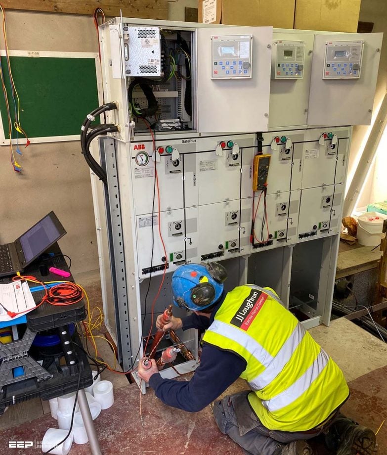
Erection includes the setting in place of these cubicles, their interconnection both mechanically and electrically, and the fitting of any extra relays together with the power and control cables. The chambers may have to be filled with insulating media of different types.
Once the equipment has been erected it needs to be commissioned, which is defined as the work of testing and finally placing in service of the installed apparatus.
The focus of this technical article will be the metal-enclosed switchgear (switchgear assemblies with an external metal enclosure intended to be earthed, and complete except for external connections), and metal-clad switchgear (metal-enclosed switchgear in which components are arranged in separate compartments with metal enclosures intended to be earthed).
1. Storage of MV switchgear
It is best to deliver the switchgear cubicles at a time convenient for their immediate erection. However, it sometimes (often) happens that the site works are delayed, in which case the switchgear must be stored carefully until it is needed.
On delivery, it is important to check that all items are present and correct in accordance with the delivery note and then to store these components carefully to ensure that no parts go astray.
If possible, arrangements should be made to keep the building temperature in excess of the dew point so that condensation on the equipment is prevented and thereby the plant is protected from corrosion.
Figure 1 – An example of medium voltage switchgear storage


2. Erection
Before commencing erection it must be ensured that the workforce is in possession of all the drawings and instructions required to erect the equipment, which is normally provided by the manufacturer. The substation in which the switchgear is to be erected should be as clean and dry as possible and all debris should have been cleared away.
During erection particular attention should be paid to a number of points:
- Dirt and debris should be excluded from partially erected cubicles.
- All openings that are not in immediate use should be blanked off or covered by clean sheets.
- All electrical insulation should be kept clean and dry by being kept covered and, if necessary, heated.
- Materials that have been issued from stores and not yet used on erection should be stored safely and tidily.
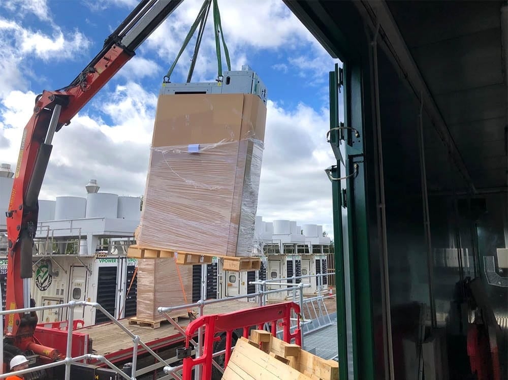
When handling the cubicles and major components care should be taken to observe the correct lifting arrangements and to make certain that slings are attached to the manufacturer’s designated lifting points. This ensures that no parts are subjected to undue strains or sudden stresses which could result in disturbed settings or other damage.
Figure 2 – Lifting the MV cubicle from the truck


2.1 Foundations
The successful erection and operation of the switchboard depend very largely on the accuracy of the foundations. The most useful form of fixing medium for the type of switchboard considered here is some form of proprietary channel embedded in the floor, containing captive adjustable nuts.
Less commonly nowadays, holes may be cast in the floor in which suitable foundation blots can be grouted after the switchgear has been erected carefully.
Figure 3 – Switchgear foundation and cable trench


2.2 General assembly
It is normal to commence the assembly of a distribution switchboard from the center unit. This minimizes any effect of a build-up of errors as the equipment is erected. Any inter-unit tie-bolts are loosely positioned as erection proceeds, and all units lined up onto the center unit.
Plumb lines should be used on each unit to ensure good alignment. When all units have been placed in position and checked for alignment, the inter-unit bolts may be tightened and checks may be made that any withdrawable portions can be entered or withdrawn smoothly.
Instrument panels and any other component details should then be added to the switchboard.
2.3 Busbar and circuit chamber assembly
The actual section of the busbars to be used should be quoted on the manufacturer’s drawings and care must be taken to ensure that the appropriate section is used for a particular unit. Some general guidelines on the preparation of contact surfaces are given below, but it cannot be overstressed that at all times the manufacturer’s instructions must be followed.
Normally, the lower busbar is connected up first, with the joints insulated as required, ensuring that a good electrical connection is made between all copper faces and that all securing nuts are tight. The next bar to be assembled will be the center one and, finally, the top one.
The same treatment of joint faces must be carried out on all other connection joints within the circuit chamber, such as connections for VTs.
Figure 4 – Medium voltage cubicles: Busbar chamber assembly


The manufacturer’s instructions should be checked carefully to see whether any or all of the joints that have been made on-site are required to be insulated. If this is the case then the components needed should have been supplied with the equipment and the instructions given by the manufacturer should be followed carefully, particularly in respect of any recommended safety precautions, with special attention to the chemical reagents that may be used.
2.4 Cabling
The preparation of the cables for connection to the switchgear is a specialist occupation and an experienced jointer should be employed for this purpose. The cable has to be laid carefully to avoid tight bends and the length of the cable lug measured very carefully to avoid any stress on the cable once the joint has finally been made. Minimum bending radii for cables are specified in BS 6480 (note that this standard is obsolete, but remains usable).
Insulation of the exposed cable and of the joint is frequently provided by means of heat-shrinkable plastics sleeves. These should be applied and terminated in accordance with the manufacturer’s specific instructions. Where proprietary cable connectors are supplied for the termination of the cables, apply these with careful reference to the termination maker’s instructions, or employ a specialist contractor.
Occasionally, paper cables are still terminated in compound-filled boxes and where this is the case care should be taken to ensure that the compound used is continually stirred during the melting period, to avoid excessive heating and possible burning of the compound at the bottom of the boiler. Care must be taken to ensure the cleanliness of the cable box and all utensils associated with this operation.
Figure 5 – Cable box connections of medium voltage switchgear type ‘Genie Evo’ by Schneider Electric


The cable box itself, and any buckets or ladles which are used in the operation, must be pre-heated before use and the compound at the appropriate temperature should be poured slowly to avoid splashing and the inclusion of air bubbles. When the cable box is filled to its indicated level, the compound should be allowed to cool slowly, avoiding draughts.
If the compound falls below the indicated level on cooling, it should be topped up while still warm to ensure a good bond between the main mass and the topping layer.
Figure 6 – Erection of switchgear


2.5 Earthing
Each unit forming part of any installation must be earthed by means of a copper strip fastened by a bolt or stud connection. This earth strip must be continuous and connected to all units and fastened to the main earth. All joints must be cleaned and treated as busbar joints. Special attention should be paid to the earthing of cable sheaths at cable glands.
Figure 7 – 11kV connectors terminating EPR cable into medium voltage switchgear


2.6 Oil filling
Where chambers have to be filled with insulating oil on site it should first be checked that the oil supplied is in accordance with the manufacturer’s recommended grade. All electrical oils must conform with BS 148 and the oils must be tested for an electrical breakdown before filling, as described in BS 148 (Recycled mineral insulating oil for transformers and switchgear – Specification).
The equipment must be filled to the indicated level, and it is advisable to fill voltage transformers (VTs) after they have been positioned on the switchgear. The indicated level is usually based on an ambient temperature of 15°C, and if the actual site temperature differs significantly from this, then due allowance should be made.
2.7 Gas filling
Gas-filled circuit-breakers or switchgear compartments are usually shipped filled. Where the design pressure is relatively high the manufacturer may avoid shipping problems by filling only to just above atmospheric pressure and topping up to the recommended filling pressure on site.
In this connection, it is necessary to understand the two defined pressure levels used in the standards for gas-filled switchgear. These are:
- the filling pressure: which is the pressure to which the enclosure is filled before being put into service, and
- the minimum functional pressure: which is the lowest pressure at which the switchgear retains all its ratings.
If this is the case, then the manufacturer’s instructions must be very carefully followed, to avoid loss or contamination of the gas.
2.8 Vacuum interrupters
It is often recommended that the integrity of the vacuum in the interrupters be checked before putting into service to ensure that no damage has been done during the shipping process. The manufacturer’s handbook should be consulted for guidance on this point since it usually involves applying a high voltage across the open contacts of the (or each) interrupter.
When a vacuum circuit breaker is commissioned or undergoes routine tests, it is very important to be able to ascertain whether or not the Vacuum Interrupter (VI) is intact before putting it back into operation.
Interrupter tester enables you to check the integrity of the vacuum interrupter quickly and conveniently by means of the known relationship between the flashover voltage and the vacuum interrupter. A suitable test voltage (DC) is applied to the breaker, and the result is known immediately.
2.9 Small wiring
It is usually necessary to complete small wiring connections between the instrument panels on adjacent cubicles and to connect external multicore cables to the control cable terminating boxes, which are usually mounted at the rear of the switchgear units.
If it is not already contained on the wiring diagram, a useful aid to ensure the correct connection for multicore cables is to list the cores in order and record the appropriate connection to be made to each core at each end of the cable.
Figure 8 – Checking small wiring in medium voltage switchgear


3. Final inspection
After the switchboard has been finally erected, all securing bolts tightened, all busbars and other connections completed, all insulation finished, cables connected and small wiring completed, a final inspection should be made.
The following is a typical, but by no means exhaustive, checklist:
- Before fitting covers, all chambers should be checked for complete cleanliness and the absence of all foreign matter.
- Once the covers have been fitted, it should be checked that all fixing screws are in place, and secure.
- All labels, where required, should be fitted and visible.
- Any mechanical interlocks should be checked; safety shutters, where fitted, must be checked to be operative.
- All withdrawable items should be proved to be capable of extraction and isolation as required.
- All fuses and links of the correct current rating should be inserted into the appropriate holders.
- All exposed insulation surfaces must be clean and dry.
- A final check should be made for continuity of earthing.
- All tools used in the erection of the switchboard should be carefully accounted for.
Sources:
- Handbook of electrical installation practice by G. Stokes
- Commissioning and maintenance of electrical power system – Keith Harker
Excellent. Can I get a pdf version?
Thanks a lot
Explanations are so exact it leaves the in no doubt. Keep it up.
Thank you Kenan.