
Fault conditions
For “protection against electric shock under fault conditions“ in TN systems, overcurrent and residual current devices have been approved. For the use of surge protective devices (SPDs) this means that these protective devices may only be arranged downstream of the devices for “protection against electric shock under fault conditions” in order to ensure that the measure to protect against life hazards also operates in the event of a failure of an SPD (surge protective device).
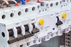
 Surge Protective Devices In TN Systems (Guide For Low Voltage Electricians); photo credit: ienergytech.com.au
If a Type 1 or 2 surge protective device (SPD) is installed downstream of a residual current device, it has to be expected that, because of the discharged impulse current to PE, this process will be interpreted as residual current by a residual current device (RCD), and it interrupts the circuit.
Equivalents for SPD classifications
(In the following lines we will use the designation SPD Type 1,SPD Type 2, SPD Type 3)
| Definition acc. to IEC 61643 | Definition acc. to EN 61643 | |
| SPDs which withstand the partial lightning current with a typical waveform 10/350 μs require a corresponding impulse test current Iimp The suitable test current Iimp is defined in the Class I test procedure of IEC 61643-1 | SPD class I | SPD Type 1 |
| SPDs which withstand induced surge currents with a typical waveform 8/20 μs require a corresponding impulse test current In The suitable test current In is defined in the Class II test procedure of IEC 61643-1 | SPD class II | SPD Type 2 |
| SPDs that withstand induced surge currents with a typical waveform 8/20 μs and require a corresponding impulse test current Isc The suitable combination wave test is defined in the Class III test procedure of IEC 61643-1 | SPD class III | SPD Type 3 |
Moreover, if an SPD Type 1 is loaded with partial lightning currents it must be assumed that the high dynamics of the lightning current will cause mechanical damage on the residual current device (Figure 1 below).
This would override the protective measure “protection against electric shock under fault conditions”.

Of course, this must be avoided. Therefore both lightning current arresters Type 1 and SPDs Type 2 should be used upstream of the residual current device. Hence, for SPDs Type 1 and 2, the only possible measure for “protection against electric shock under fault conditions” is using overcurrent protective devices.
The following maximum continuous voltages apply to SPDs Type 1, 2 and 3 when used in TN systems (Figures 2 and 3 A to B):

TN-C-S systems
Figure 4 illustrates an example of the connections for use of lightning current arresters and surge protective devices in TN-C-S systems.

It can be seen that SPDs Type 3 are used downstream of the residual current device (RCD). In this context, please note the following:
As a result of the frequency of switching surges in the terminal circuits, SPDs Type 3 are primarily employed to protect against differential mode voltages. These surges generally arise between L and N.
A surge limitation between L and N means that no impulse current is discharged to PE. Thus, this process can also not be interpreted as residual current by the RCD. In all other cases, SPDs Type 3 are designed for a nominal discharge capacity of 1.5 kA. These values are sufficient in the sense that upstream protective stages of SPDs Type 1 and 2 take over the discharge of high energy impulses. When using an RCD capable of withstanding impulse currents, these impulse currents are not able to trip the RCD or cause mechanical damage.
TN-S systems
The Figures 5 to 9 illustrate the use of SPDs as part of the lightning protection zones concept, and the required lightning and surge protective measures for a TN-C-S system.
Use of SPDs in TN-S systems // Example

SPDs used in TN systems // Examples
Example 1 // Office Building – Separation of the PEN in the main distribution board

Example 2 // Office Building – Separation of the PEN in the subdistribution board
Example 3 // Industry – Separation of the PEN in the subdistribution board
Example 4 // Residential building
Reference // Lightning protection guide – DEHN + SÖHNE


thank you for the information i really like to know more…