
Surge protective devices (SPDs) and RCDs
Where the power distribution system incorporates RCDs transient activity could cause RCDs to operate and hence loss of supply. Surge protective devices (SPDs) should wherever possible be installed upstream of RCD to prevent unwanted tripping caused by transient overvoltages.
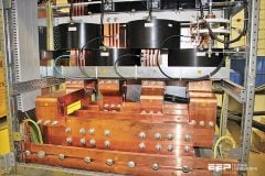
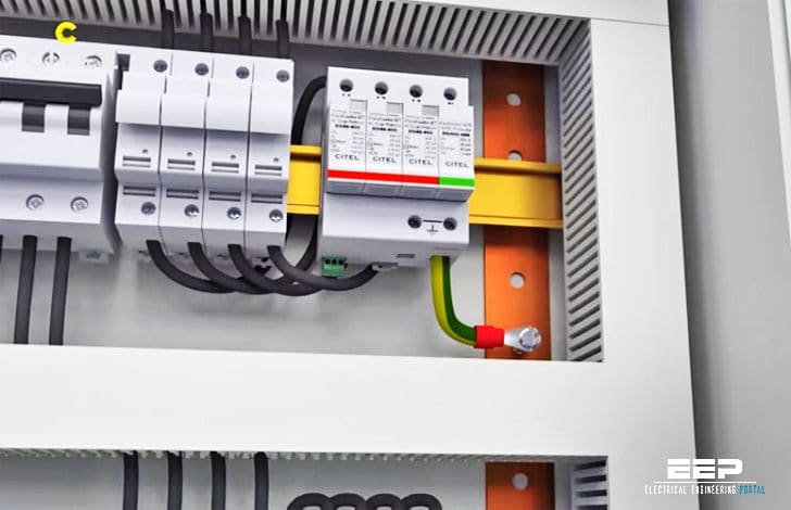 Best practice for using surge protective devices (SPDs) and RCD together (photo credit: CITELSurgeProtectors via Youtube)
Where surge protective devices are installed in accordance with BS 7671 534.2.1 and are on the load side of a residual current device, an RCD having an immunity to surge currents of at least 3 kA 8/20, shall be used.
If the SPD is installed downstream of the RCD, the RCD should be of the time delayed type with an immunity to surge currents of at least 3kA 8/20. Section 534.2.2 of BS 7671 details the minimum SPD connection requirements (based on the SPD modes of protection) at the origin of the installation (typically a Type 1 SPD).
In case you are not familiar with surge protective devices operation and types, you better read first the basics of surge protective devices.
SPD connection type 1 (CT1)
An SPD configuration based on connection type 1 (CT1) is for TN-C-S or TN-S earthing arrangements as well the TT earthing arrangement where the SPD is fitted downstream of the RCD.
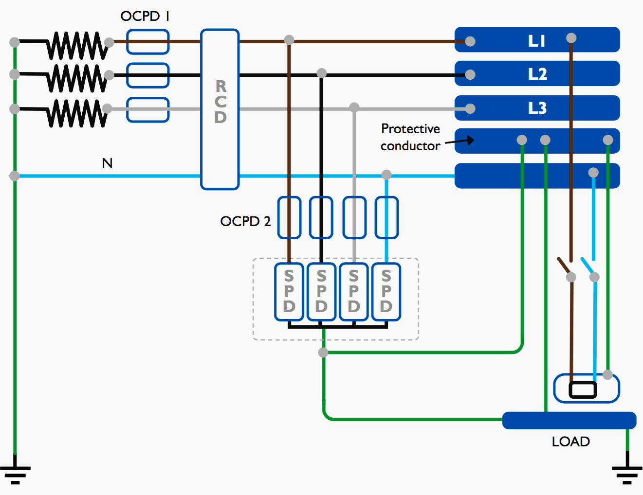
In general, TT systems require special attention because they normally have higher earth impedances which reduces earth fault currents and increases the disconnection times of Overcurrent Protective Devices – OCPDs.
Therefore in order to meet the requirements for safe disconnection times, RCDs are used for earth fault protection.
SPD connection type 2 (CT1)
An SPD configuration based on connection type 2 (CT2) is required on a TT earth arrangement if the SPD is upstream of the RCD. The RCD being downstream of the SPD would not operate should the SPD become defective.
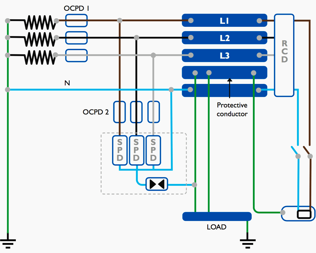
The SPD arrangement here is configured such that the SPDs are applied between the live conductors (live to neutral) rather than between live conductors and the protective conductor.
Should the SPD become defective it would therefore create a short circuit current rather than an earth fault current and as such would ensure that the overcurrent protective devices (OCPDs) in-line with the SPD safely operates within the required disconnection time.
Clause 534.2.3.4.3 therefore advises that the SPD between neutral and the protective conductor is rated at 4 times the magnitude of the SPD between the live conductors.
Therefore, only if the impulse current Iimp cannot be calculated, 534.2.3.4.3 advises that the minimum value Iimp for an SPD between neutral and the protective conductor is 50kA 10/350 for a 3 phase CT2 installation, 4 times 12.5kA 10/350 of the SPDs between the live conductors.
The CT2 SPD configuration is often referred the ‘3+1’ arrangement for a 3 phase supply.
SPDs and TN-C-S earth configurations
The minimum SPD connection requirements at or near the origin of the installation for a TN-C-S system requires further clarification as Section 534 of BS 7671 illustrates (see Figure 3 below) a Type 1 SPD being required between the live and PE conductors – the same as required for a TN-S system.
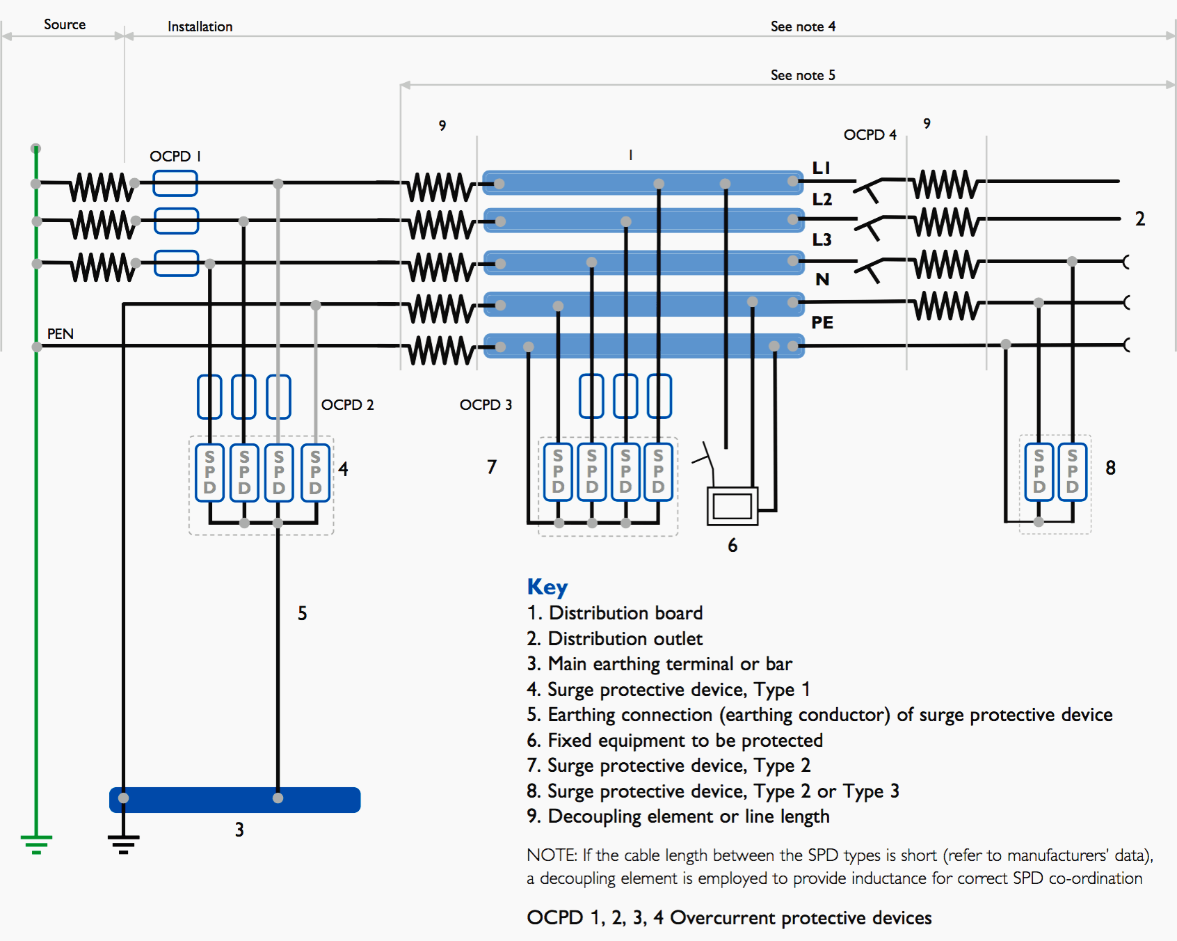
The term ‘at or near the origin of the installation’ creates ambiguity given the fact that the word ‘near’ is not defined. From a technical point of view, if SPDs are applied within a 0.5m distance of the PEN split to separate N and PE, there is no need to have an SPD protection mode between N and PE as shown in the figure.
If BS 7671 would allow the application of SPDs to the TN-C side (utility side) of the TN-C-S system (observed in some parts of Europe), then it may be possible to install SPDs within 0.5m of the PEN split to N and PE and omit the N to PE SPD protection mode.
As Type 1 SPDs are specifically installed to prevent the risk of loss of human life (to BS EN62305) through dangerous sparking which could present a fire hazard for example, in the interests of safety alone, the engineering judgement is that an SPD should be fitted between N and PE for a TN-C-S system as it would in a TN-S system.
In summary, as far as Section 534 is concerned, TN-C-S systems are treated the same as TN-S systems for the selection and installation of SPDs.
The basics of surge protection devices
A Surge Protection Device (SPDs)is a component of the electrical installation protection system. This device is connected to the power supply in parallel with the loads (circuits) that it is intended to protect (see Figure 4). It can also be used at all levels of the power supply network.
Principle of Surge Protection Operation
SPDs are designed to limit transient overvoltages due to lightning or switching and divert the associated surge currents to earth, so as to limit these overvoltages to levels that are unlikely to damage the electrical installation or equipment.

Types of surge protection devices
There are three types of SPD according to international standards:
Type 1 SPD
Protection against transient overvoltages due to direct lightning strokes. The Type 1 SPD is recommended to protect electrical installations against partial lightning currents caused by direct lightning strokes. It can discharge the voltage from lightning spreading from the earth conductor to the network conductors.
Type 1 SPD is characterised by a 10/350µs current wave.

Type 2 SPD
Protection against transient overvoltages due to switching and indirect lightning strokes. The Type 2 SPD is the main protection system for all low voltage electrical installations. Installed in each electrical switchboard, it prevents the spread of overvoltages in the electrical installations and protects the loads.
Type 2 SPD is characterised by an 8/20µs current wave.
Type 3 SPD
Type 3 SPD is used for local protection for sensitive loads. These SPDs have a low discharge capacity. They must therefore only be installed as a supplement to Type 2 SPD and in the vicinity of sensitive loads. They are widely available as hard wired’ devices (frequently combined with Type 2 SPDs for use in fixed installations).
However they are also incorporated in:
- Surge protected socket outlets
- Surge protected portable socket outlets
- Telecoms and Data protection
Reference // BEAMA Guide to Surge Protection Devices (SPDs): selection, application and theory


Very informative , thank you for publishing since bs 7671 18 th edition made it compulsory to install SPD s , this is very relevant important topic.
Under SPD connection type 1 (CT1), the pictorial presentation is that of TT earthing system, because it shows separate earth at Load end.
Though “Primarily” CT1 is for TN-C-S & TN-S
Kindly share Electrical related topics.