
Power distribution
Power distribution systems are used in every residential, commercial, and industrial building to safely control the distribution of electrical power throughout the facility. Most of us are familiar with the power distribution system found in the average home.
Power purchased from a utility company enters the house through a metering device. The power is then distributed from a load center to various branch circuits for lighting, appliances, and electrical outlets.
The role of a switchboard is to divide the main current provided to the switchboard into smaller currents for further distribution and to provide switching, current protection, and metering for these various currents.
There are multiple elements that make up a switchboard. Included in the list of elements are a frame, buses, overcurrent protective devices, service metering, and outer covers.
Switchboard Frame
The frame of the switchboard houses and supports the other components. The standard Siemens switchboard frame is 90 inches high and 32 or 38 inches wide. An optional height of 70 inches with widths of 32, 38, or 46 inches is also available. Siemens switchboards have a depth measurement ranging from 20 to 58 inches.

Bus
A bus is a conductor or set of conductors that serves as a common connection for two or more circuits. NEC® article 408.3 states that bus bars shall be located so as to be free from physical damage and shall be held firmly in place.
NEMA Phase Arrangement
Bus bars are required to have phases in sequence so that an installer can have the same fixed-phase arrangement in each termination point in any switchboard. This is established by NEMA (National Electrical Manufacturers Association). If a non-NEMA phase sequence is used, it must be marked on the switchboard.
Buses are mounted within the frame. Horizontal bus bars are used to distribute power to each switchboard section. Vertical bus bars are used to distribute power via overcurrent devices to the load devices. Bus bars are made of tin-finished aluminum or silver-finished copper. Bus bars may either be temperature rated or current density rated.
The current density rating specifies the maximum current per square inch of a bus bar cross section.

The following rear view drawing of a switchboard illustrates vertical and horizontal bus bar connections. The vertical phase bus bars appear to be in reverse order because they are viewed from the rear, but are in the proper NEMA order as viewed from the front.
In this drawing the connector can be clearly seen on the neutral bus. Compression lugs provided on this switchboard accept properly sized incoming power cables.

Splice Plates
Splice plates are used to join the horizontal bus bars of adjoining switchboard sections, as illustrated in the following rear view drawing. To make additional distribution sections easier to install when they are needed, the horizontal bus is extended and pre-drilled to accept splice plates.
A new section is set flush against an existing section. The old and new sections are connected together with splice plates.
Through-bus
The extended horizontal bus is also referred to as through-bus. Because the load requirements in downstream distribution sections are generally less than in upstream service sections, the capacity of the through-bus is tapered, or reduced, downstream as the load falls off.
Full-capacity, or non-tapered, through-bus is available as an option. The ampacity of non-tapered through-bus remains constant throughout the switchboard.

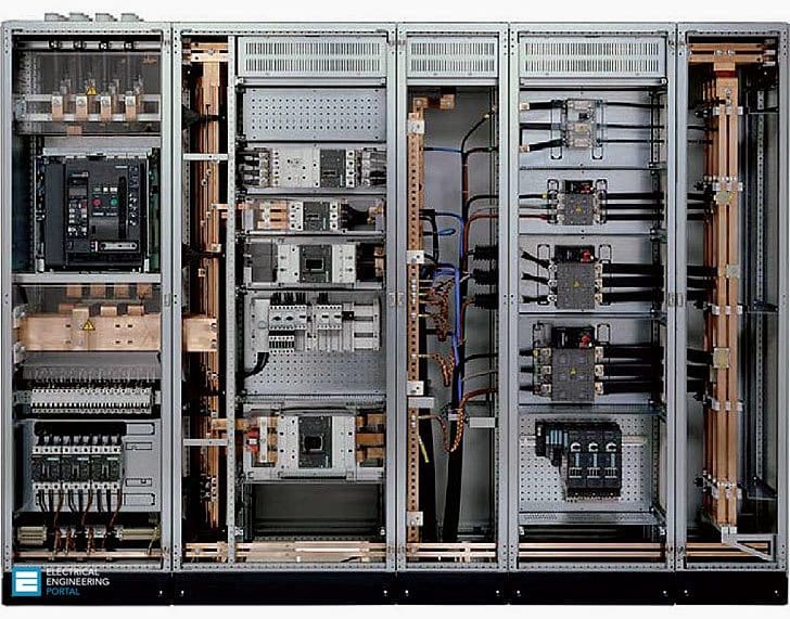
Overcurrent Protective Devices
Operator components are mounted on the front side of the switchboard.
This includes overcurrent protective devices, such as circuit breakers and disconnect switches. These devices are mounted to the bus bars using straps connected to the line side of the devices.

Outer Covers
Cover panels are installed on the switchboard so that no live parts are exposed to the operator. The front cover is referred to as the dead front. The panels are also used as trim to provide a finished look to the switchboard.
Pictorial Diagram
Simplified drawings, such as one-line, block, or pictorial diagrams are often used to show the circuits associated with a power distribution system. For example, the following pictorial diagram shows a two section switchboard.
Reference: Siemens – Basics of Switchboards


Dear Sir,
We need to make one switchboard with 3 X 30KW generators, and it have load sharing controller.How to design busbar for this configuration. 415V,50Hz, 3 Phase with neutral.
Sir, any recommendation how to fabricate withdrawal type switchboard?…
dear
i have a some issues starting of 1.2 MW 6.6 kv motor.we used soft starter for starting.
6 MW gas turbine generator for generation.
issued… when start the motor then voltage drop the LV Bus Bar and trip the LV ACB.
1. What is behaviour of generator during motor start?
2. What is base load while starting motor?
Electrical construction encompasses the installation, design, wiring, testing and maintenance of electrical systems and equipment. This type of work is critical for the safety of commercial and industrial facilities, and requires a strong skillset of electrical and wiring expertise.
We have new inquiry for Electric items. Could you please provide us email address to contact.
Thank you.
Hi, Sir i have a question regarding the calculation of CB in switchboard by witch formula we are able to calculate the value of switchboard? i really be much appreciated you if you help me .
You must know rated current of the load on each circuit breaker. This leads you to the load, the information you must have (or calculate) according to the customer’s inputs.
another question sir.. about to the construction…what material are the board to be made, and what type of framework is to be use?
i have a question to you sir… is this switchboard to have remote mechanical or remote electrical control? why?
i have a question to you sir… is this switchboard to have remote mechanical or remote electrical control? why?
Well, it must have either mechanical or electrical control. if you want to remote close or open CB’s contacts (with open and closing coil) from some distance place like control center (with SCADA, etc.), then you must have motor spring to charge it.
If you don’t have any remote control, then you use just mechanical control on the circuit breaker (open/close button).
thats very good
Thank you Khan! Glad you like it, this SIEMENS’s guide is really good.