
Estimated Study Time: 33 minutes
MV Switchgear Control Circuits
Control circuits are vital to the operation of medium voltage switchgear. The integrity of these control circuits is essential to the switchgear’s proper operation, so commissioning and maintenance activities records are extremely important for troubleshooting practices. Furthermore, one has to comprehend the reading and interpretations of the control circuits in order to develop the skills of troubleshooting and sequence of operation follow.
 Mastering switchgear control circuits – AC/DC circuits and circuit breaker closing circuit
Although the control circuits are many, they boil down to the circuit breaker close/trip coils irrespective of the many details involved.
The good news is that the principles addressed in this technical article apply to almost all types of switchgear with some exceptions. The control circuits for Gas Insulated Substation (GIS), for example, are much more detailed and complicated, but they have many common principles with 13.8 kV switchgear.
Hence, it is extremely important to master the skills of control circuit interpretation for better and faster troubleshooting activities.
In addition, a brief view of busbar arrangements utilized in different applications is introduced, as it has a direct effect on the interlocking contacts that might be used in the control circuits. The next article will talk about substation single-line diagram, circuit breaker tripping circuit, bay-control-protection-unit (BCPU) and alarm circuits, indication circuits, and mechanical/electrical interlocking circuits.
- Busbar Arrangement Overview
- Switchgear Components
- Substation Single-Line Diagram
- Substation Control Systems
- About My Next Article (Trip Coils, Control/Alarm Circuits, Interlocking Schemes)
1. Busbar Arrangement
A variety of busbar configurations exist in which there is a trade-off in complexity, cost, and reliability. The main criteria for selecting the busbar arrangement are summarized below.
- Simplicity.
- Ease of equipment maintenance.
- Outage duration during maintenance.
- Future provision of extension with demand growth.
The most common practices for the three major substation types are as below:
1. Generation stations:
- Large generators:
- Double bus, single breaker
- Double bus, double breaker
- Combination double/single, with double breakers for the generator circuits and a single breaker for outgoing lines or transformers
- Double bus, breaker and a half
- Small generators:
- Single bus
- Various forms of line tap
2. Network switching stations:
- Breaker and a half
- Double bus, usually single breaker
- Single bus, single breaker
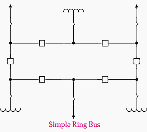
- Ring bus
3. Major transformer stations:
- High-voltage side
- Ring bus
- Single bus, double section
- Double bus
- Breaker and a half
- Low-voltage side
- Single bus, double section
- Double bus
4. Minor transformer stations:
- High-voltage side:
- Single breaker tap
- Three-breaker line loop
- Disconnect only tap
- Low-voltage side:
- Single bus, single or double section
The configurations listed above offer different levels of reliability and service continuity as opposed to cost and complexity.
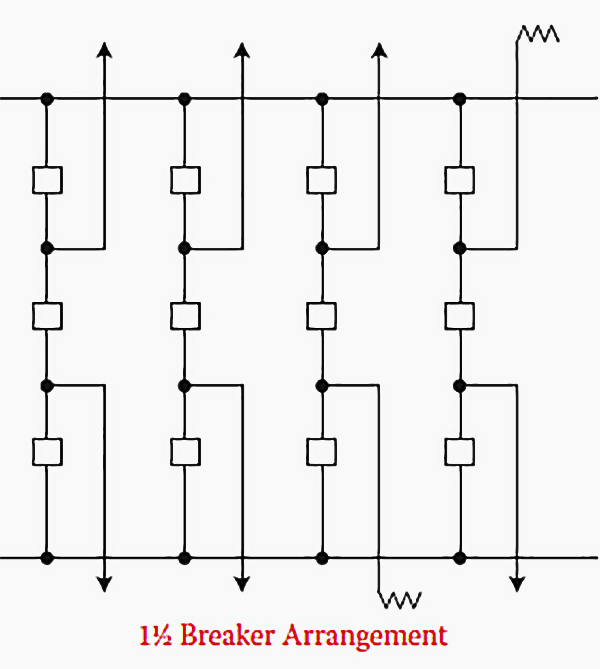
Hence, any circuit breaker can be taken out of service without power flow interruption through a given substation (see Figure 1 and Figure 2 above). This high level of service continuity and reliability do not always hold for other configurations, so one has to make the proper configuration as per design objectives.
Recommended Reading – The Essentials Of Substations, Electrical Equipment and Busbar Arrangements
The Essentials Of Substations, Electrical Equipment and Busbar Arrangements
2. Switchgear Components
Main components housed inside switchgear cubicles are:
- Busbar: a metallic strip or bar enclosed inside switchgear for high current applications
- Switching devices: circuit breakers, switches, fuses, disconnectors (isolators), contactors, load-break switches, ground switch, and surge arrestors,
- Instrument transformers: Current and voltage transformers used for current and voltage transformation for metering and protection purposes
- Auxiliary relays: Relays assisting another relay or device in performing an action
- Miniature circuit breakers: breakers used in control compartments
- Protective relays
- Auto recloser / Sectionalizer: Equipment used to restore power promptly after transient faults
Recommended Reading: – Switching devices you are likely to spot in every medium voltage switchgear
Switching devices you are likely to spot in every medium voltage switchgear
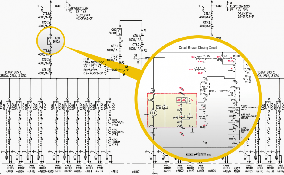
3. Substation Single-Line Diagram
Substation single-line diagram (SLD) offers some detailed descriptions of the switchgear components and specifications. Figure 3 illustrates a single bus, double section busbar arrangement. Two incomers tied through a bus-tie breaker and each bus section has 12 feeders.
Related electrical guides & articles


Salem Alshahrani
Electrical engineer (BEE & Meng). Specialized in substation design, especially in LV/MV switchgears and transformers. Passionate in power system planning, analysis, and stability studies.Profile: Salem Alshahrani
