Medium Voltage Switchgear Control Circuits
In the previous article, an introductory part of the switchgear control circuits, including DC/AC circuits and breaker closing circuit, was discussed thoroughly. This article continues the discussion with a breaker trip circuit, bay control-protection unit (BCPU) & alarm circuit, indication circuit, and interlock circuit.
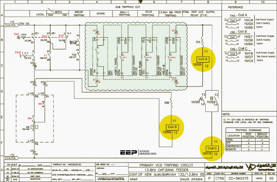
Fortunately, the main principles are the same, meaning that the tools used in the last article are good for this article, too. These principles are related to the contact default status, drawing reading basics, etc.
One of the main concepts is the breaker default position, which is charged spring, test position, open status.
- Switchgear Auxiliary Switches
- Circuit Breaker Tripping Circuit
- Bay Control-Protection Unit (BCPU) and Alarm Circuit
- Indication Circuit
- Mechanical Interlocking Circuit
1. Switchgear Auxiliary Switches
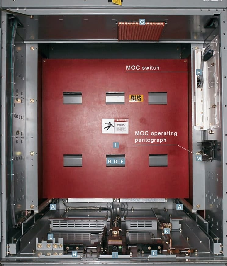
Some might ask how the breaker statues are signaled into the control circuits. Well, different types of auxiliary switches signify the breaker position and provide electrical interlocks. These auxiliary switches are known as mechanism operated (MOC switches) and truck operated (TOC switches) auxiliary switches.
MOC switches are mounted on the breaker, but often they are mounted on the cubicle with a mechanical link to the breaker. The MOC switches often are used to signal the breaker open/close status quo and any update in its operating mechanism.
The TOC switches, also, are mounted on the cell and they operate when the breaker is moved to the operating position. That is, the switches change their states when the breaker moves from test position to service position.
They are used for interlocking and remote position indication.
