
Substations & distribution switchgears
The subject of this article is to discuss few most common types of MV/HV power substations based on the type of distribution switchgear, which can be seen in every distribution network. There are a number of methods of construction of substations depending on the switchgear type.
 Five substation construction types you should recognize (photo credit: ФСК ЕЭС)
The four most common types are described below.
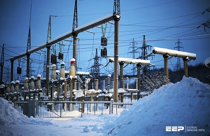
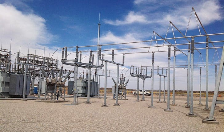
1. Open air substations
Open air substations contain separately mounted and interconnected switching equipment and components, like current transformers (CTs), voltage transformers (VTs), busbar support insulators, cable sealing ends, etc., where atmospheric air provides the main insulation path to earth.
This is very important requirement and it requires relatively large clearances and, in consequence, open-air substations tend to cover large ground areas. Also, if substation is located near local communities, they’re usually not very happy about its location.
Some degree of landscaping is normally required to minimize the visual impact.
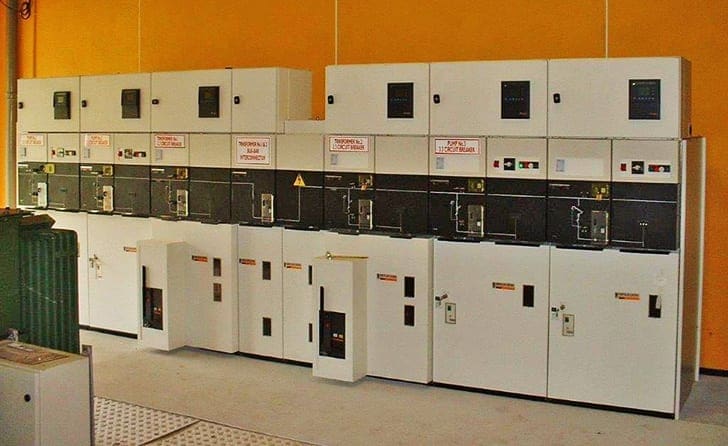
2. Metal enclosed
With metal enclosed arrangement all switching devices and associated components are enclosed in a metallic earthed structure on a per-bay basis and are cable connected.
This arrangement has the disadvantage that there is no segregation within the panel. Hence, a fault in an instrument transformer, e.g., could readily spread to encompass the switching device and panel interconnecting busbars.
Such arrangements are not generally used where high-reliability and high-availability systems are required, i.e. at bulk supply points or at primary distribution substations.
Metal-enclosed substations may be either of the outdoor type, in which case the enclosure must protect the internally connected equipment against all prevailing environmental conditions, or alternatively the substation may be enclosed within a building or low-cost weatherproof housing.
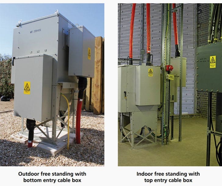
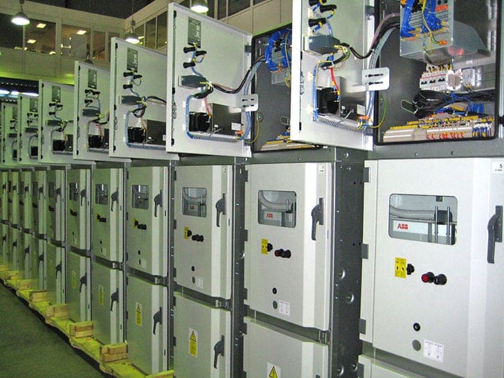
3. Metal-clad
This is a derivative of the metal-enclosed switchgear where all major components per bay are physically segregated from one another by means of earthed metalwork such that a fault in any one compartment cannot readily spread to adjacent compartments.
It is vitally important that busbars are unaffected by a fault in any particular circuit panel so that adjacent panels can safely remain in service until appropriate repairs can be executed. Typical segregation is between cable box and instrument transformers, instrument transformer chambers and circuit-breaker and circuit-breaker and busbars.
Most primary switchboards are of the metal-clad type. For economic reasons many such switchboards were originally designed for outdoor use. However, in harsh environmental climates environmental deterioration may readily occur and maintenance costs may be high.
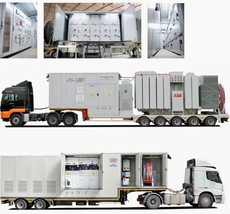
It is now common policy for such metal-clad switchgear to be housed in appropriate weatherproofed buildings.
A further modern trend is for them to be housed in transportable containers (mobile substations) such that, as systems and local load patterns change, they can readily be transferred to more appropriate locations.
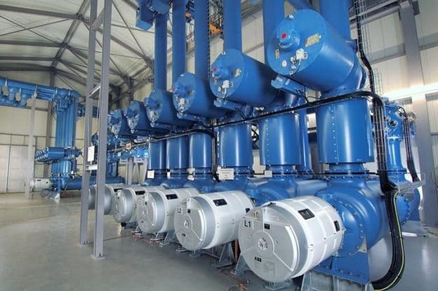
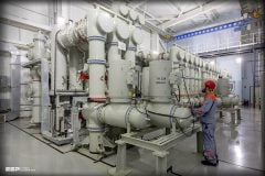
4. Gas-insulated substations (GIS)
A further form of metal-clad substation that is used mainly at transmission voltages is the gas-insulated substation. With this concept SF6 provides the main dielectric medium between the primary conductor and earth.
In view of the very high dielectric strength of SF6 the dimensions can be made very small.
Both arrangements are widely used, with the phase-isolated concept being used mainly at higher voltages and the three phases in one tank concept being used at the lower transmission, or high distribution, voltages, i.e. 132 kV.
Some manufacturers have, however, utilised the phase-isolated concept down to voltage levels of 33 kV, and there are a number of such installations within the UK.
Insulation considerations
Correct insulation design is vital for all substations. This applies not only for openair types and insulation-enclosed types but also for metal-enclosed and metal-clad types, which employ many insulating components.
For example with metal-clad equipment connections must be provided to connect one compartment to adjacent compartments. Such connections are usually by means of bushings. Insulation has also to be provided between phases and between phase and earth.
Typical insulating materials that may be employed are:
- Atmospheric air,
- Insulating oil,
- Bitumous compound,
- Oil-impregnated paper (OIP),
- Synthetic resin bonded paper (SRBP) epoxy resin or
- SF6.
The correct design of insulating interfaces between components and different insulation materials is vital for the long-term service integrity of the equipment.
Loss of Service Continuity (LSC)
When the accessibility of the switchgear compartments are known, then the consequences of opening a compartment on the operation of the installation can be predicted. Loss of Service Continuity (LSC) classification is defined by the IEC:
By IEC: Category defining the possibility to keep other high-voltage compartments and/or functional units energised when opening a accessible high-voltage compartment”.
Generally, the rule is that if no accessible compartment is provided, then the LSC classification does not apply on that compartment.
Terms like ‘metal-clad’ or ‘metal-enclosed’ fall under classification of LSC. There are few LSC categories defined:
LSC1 – If any other switchgear functional unit than the one under intervention has to be switched off, then service is partial only: LSC1
LSC2 – If at least one set of busbars can remain live, and all other functional units can stay in service, then service is optimal: LSC2
LSC2A/B – If within a single functional unit, other(s) compartment(s) than the connection compartment is accessible, then suffix A or B can be used with classification LSC2 to distinguish whether the cables shall be dead or not when accessing this other compartment.
Reference // High-Voltage Engineering and Testing by Hugh M. Ryan; The Institution of Engineering and Technology (Purchase hardcover from Amazon)


Excellent
Great work guys
Learning portal
Hi, guys. I am looking for a comprehensive laboratory guide for protection relays testing considering high voltage networks of 150kV and 400kV.