Search

Premium Membership ♕

Experience matters. Learn from experienced electrical engineers. Study specialized LV/HV technical articles, papers and courses.

Home / Technical Articles / Switching contactor and effect of long control lines

Voltage drop

In accordance with IEC 60947-4-1 and IEC 60947-5-1, the normal control voltage range of power and control contactors lies between 85 … 110 % of the rated control voltage. Within these limits contactors pull-in perfectly.
Switching contactor and effect of long control lines

Frequently contactors are offered with an extended control voltage range, thus for example with contactors with electronic coil control. The technical documentation of the devices used is definitive.

At small control voltages and with long control lines, the voltage drop across the lines to the contactor (both out-going and return conductors should be considered!) can be so big that pulling-in reliably is no longer guaranteed. In addition to burnt coils, another consequence of this may be welding of the main contacts.

It must therefore be ensured that taking into account:

  1. Supply voltage variations
  2. Voltage drop at the control transformer at peak load and
  3. Voltage drop across the control lines the minimum pull-in voltage is always guaranteed.

For the voltage drop across the control lines the following applies approximately:

Voltage drop across the control lines

or for the maximum line length at a given permissible voltage drop:

Maximum line length at a given permissible voltage drop

  • l – Line length (supply and return line) [m]
  • lmax – maximum line length (feeding and return line) [m]
  • uR – Percentage voltage drop [%]
  • UC – Rated control voltage [V]
  • S – Pickup power of the contactor [VA] κ Conductivity of the conductor material [m·Ω-1·mm-1] = 57 for copper
  • A – Conductor cross section [mm2]
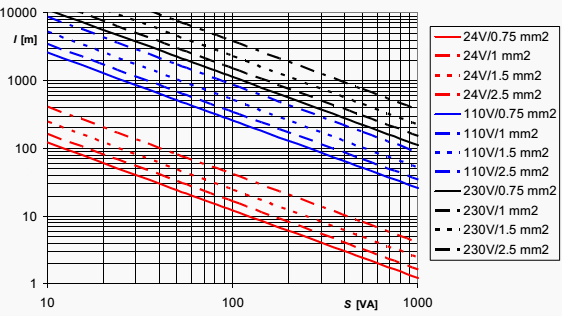
Line lengths for a voltage drop of 5 % and copper conductors
Figure 1 – Line lengths for a voltage drop of 5 % and copper conductors

l – Line length (feeding and return line)
S – Apparent power of load


Effect of the cable capacitance

With AC controls with long control lines, low coil power ratings of the contactors and high control voltage, depending on the topography of the circuit, the capacitance of the control line can be in parallel to the controlling contact and practically bypass it when it is open.

This can mean that when the control contact has opened sufficient current continues to flow via the cable capacitance causing the contactor not to drop out. An example may be a contactor that is controlled by a distantly located sensor (for example limit-switch).
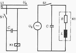
When the control contact switches off the cable to the contactor, the capacitance of the line causes at most a slight drop-off delay.
Figure 2 – When the control contact switches off the cable to the contactor, the capacitance of the line causes at most a slight drop-off delay.

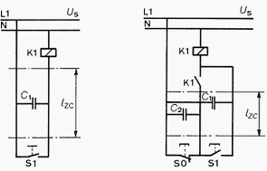
If the long control line to the contactor stays live when the control contact is open, the current via the cable capacitance can prevent the contactor from dropping out. With pulse contact control, the capacitance of the lines acts twice, whereby the permissible line length is halved.
Figure 3 – If the long control line to the contactor stays live when the control contact is open, the current via the cable capacitance can prevent the contactor from dropping out. With pulse contact control, the capacitance of the lines acts twice, whereby the permissible line length is halved.

A worked example would be:

I= 0.25 ICN
U= 0.6 UC
cos φ = 0.3

IH – Holding current of the contactor
ICN – Rated current the contactor coil
UH – Drop-out voltage of the contactor
UC – Control voltage
cos φ – Power factor of the contactor coil (on-state)

The permissible cable capacitance is calculated at 50 Hz approximately to be:

CZ ≈ 500 · SH/UC2 [μF]

CZ – Permissible cable capacitance [μF]
SH – Holding power at UC[VA]
UC – Control voltage [V]

At a typical cable capacitance of 0.3 μF/km the permissible line length for maintained contact control is:

Permissible line length formaintained contact control

With momentary contact control the line length is halved. Graphic presentation for the control voltages 110 V and 230 V see Figure 4. As the cable capacitance is very much dependent on the type of cable, it is recommended in case of doubt to obtain the specific value from the manufacturer or to measure it.
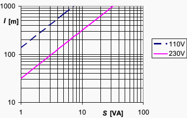
Permissible line length in accordance with the above conditions for maintained contact control at control voltages of 110 V and 230 V at 50 Hz
Figure 4 – Permissible line length in accordance with the above conditions for maintained contact control at control voltages of 110 V and 230 V at 50 Hz

l – Line length
S – Apparent power (holding power) of the contactor

If there are problem with respect to the permissible line length because of the line capacitance the following measures are possible in accordance with above discussion:

  • Application of an additional load (resistor parallel to contactor coil)
  • Use of a larger contactor with bigger holding power
  • Use of a lower control voltage
  • Use of direct voltage

Reference // Allen Bradley Low Voltage Switchgear and Controlgear // Rockwell Automation

Premium Membership

Get access to premium HV/MV/LV technical articles, electrical engineering guides, research studies and much more! It helps you to shape up your technical skills in your everyday life as an electrical engineer.
More Information
Edvard Csanyi - Author at EEP-Electrical Engineering Portal

Edvard Csanyi

Hi, I'm an electrical engineer, programmer and founder of EEP - Electrical Engineering Portal. I worked twelve years at Schneider Electric in the position of technical support for low- and medium-voltage projects and the design of busbar trunking systems.

I'm highly specialized in the design of LV/MV switchgear and low-voltage, high-power busbar trunking (<6300A) in substations, commercial buildings and industry facilities. I'm also a professional in AutoCAD programming.

Profile: Edvard Csanyi

3 Comments


  1. AKHIL S M
    Aug 07, 2019

    Could you please tell me how the constant 500 came.


  2. Mohamed Said Taha`
    Jul 27, 2018

    How can i size the resistor parallel to contactor coil to avoid capacitance effect?


  3. Prashant
    Dec 16, 2013

    hello
    I am an electrical engineer.
    i had experience 5years in this field.
    LV and Automation switchgear.
    I would like to request you that can you please give me technical suggestion if i have some doubt regards electrical switchgear and auotmation.

Leave a Comment

Tell us what you're thinking. We care about your opinion! Please keep in mind that comments are moderated and rel="nofollow" is in use. So, please do not use a spammy keyword or a domain as your name, or it will be deleted. Let's have a professional and meaningful conversation instead. Thanks for dropping by!

eight  +  two  =  

Learn How to Design Power Systems

Learn to design LV/MV/HV power systems through professional video courses. Lifetime access. Enjoy learning!

EEP Hand-Crafted Video Courses

Check more than a hundred hand-crafted video courses and learn from experienced engineers. Lifetime access included.
Experience matters. Premium membership gives you an opportunity to study specialized technical articles, online video courses, electrical engineering guides, and papers written by experienced electrical engineers.