MV switchgear up to and including 52 kV
Up to and including 52 kV voltage range is generally referred to as “medium voltage”. This technical article shed some light on a few devices you are likely to spot in most of the medium voltage switchgears. But, before diving into technical details, it’s a good idea to remind ourselves of important terms and definitions relating to MV switchgear.
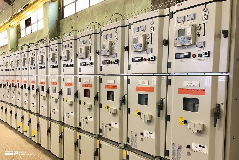
Let’s start this article with a few basic terms used later. After, the seven most common MV switching devices will be explained in detail, referring to the ABB’s equipment as an example.
Basic terms (reminder)
Term № 1 – Disconnectors
Disconnectors are mechanical switching devices which provide an isolating distance in the open position. They are capable to open or close a circuit if either a negligible current is switched or if there is no significant change in voltage between the terminals of the poles.
Term № 2 – Isolating distances
Isolating distances are gaps of specified dielectric strength in gases or liquids in the open current paths of switching devices. They must comply with special conditions for the protection of personnel and installations and their existence must be clearly perceptible when the switching device is open.
Term № 3 – Switches
Switches are mechanical switching devices, which not only make, carry and interrupt currents under normal conditions in the network but also must carry for a specific time and possibly make currents under specified abnormal conditions in the network (e.g. short circuit).
Term № 4 – Switch disconnectors
Switch disconnectors are switches which satisfy the requirements for an isolating distance specified for a disconnector in their open position.
Term № 5 – Circuit breakers
Circuit-breakers are mechanical switching devices able to make, carry and interrupt currents occurring in the circuit under normal conditions, and can make, carry for a specified time and break currents occurring in the circuit (e.g. short circuit) under specified abnormal conditions.
Term № 6 – Earthing switches
Earthing switches are mechanical switching devices for earthing and short-circuiting circuits. They we capable of carrying currents for a specified time under abnormal conditions (e.g. short circuit).
Earthing switches are not required to carry normal operating currents.
Term № 7 – Fuses
Good old fuses are switching devices that open the circuits in which they we installed by the melting of one or more parts specified and designed for the purpose of breaking the current when it exceeds a given value for a sufficiently long period.


- Disconnectors
- Switch-disconnectors
- Earthing switches
- HRC fuse links
- Short-circuit current limiter
- Circuit-breaker
- Vacuum contactors
1. Disconnectors
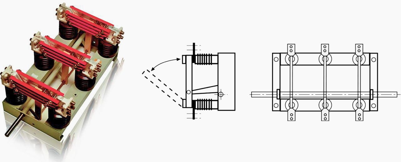
The classic design of the disconnects is the knife-contact disconnector (see Figure 1). It has become less common with the increasing use of withdrawable circuit-breakers and switch-disconnectors. This functional principle is more frequent in gas-insulated switchboard (GIS) technology.
The blades of knife-contact disconnectors installed in en upright or hanging position must be prevented from moving by their own weight.
Disconnectors can be actuated manually and, in remotely operated installations, by motor or compressed-air drives.


2. Switch-disconnectors
Switch-disconnectors are increasingly being used in distribution networks for switching cables and overhead lines. Switch-disconnectors in connection with HRC fuses are used for protection of smaller transformers. Switch-disconnectors are switches that in their open position meet the conditions specified for isolating distances.
General purpose switches can make and break all types of operating currents in fault-free operation and in the event of earth faults. They can also make and conduct short-circuit currents.


Knife-contact switch-disconnectors as per Figure 2 and rod-type switch-disconnectors as shown in Figure 3 are actuated in two ways, depending on their type:
- “Snap-action mechanism”, also referred to as toggle-spring mechanism. With this type of operating mechanism, a spring is tensioned and released shortly before the operating angle is completed and its release force actuates the main contact systems. This is used for both closing and opening.
- “Stored-energy mechanism”. This mechanism has one spring for closing and a second spring for opening. During the closing operation, the opening spring is simultaneously tensioned and latched. The stored energy for the opening operation is released by magnetic type or the striker pin of the HRC fuse.
The rod-type switch-disconnectors also enable very small phase spacings without phase barriers.


3. Earthing switches
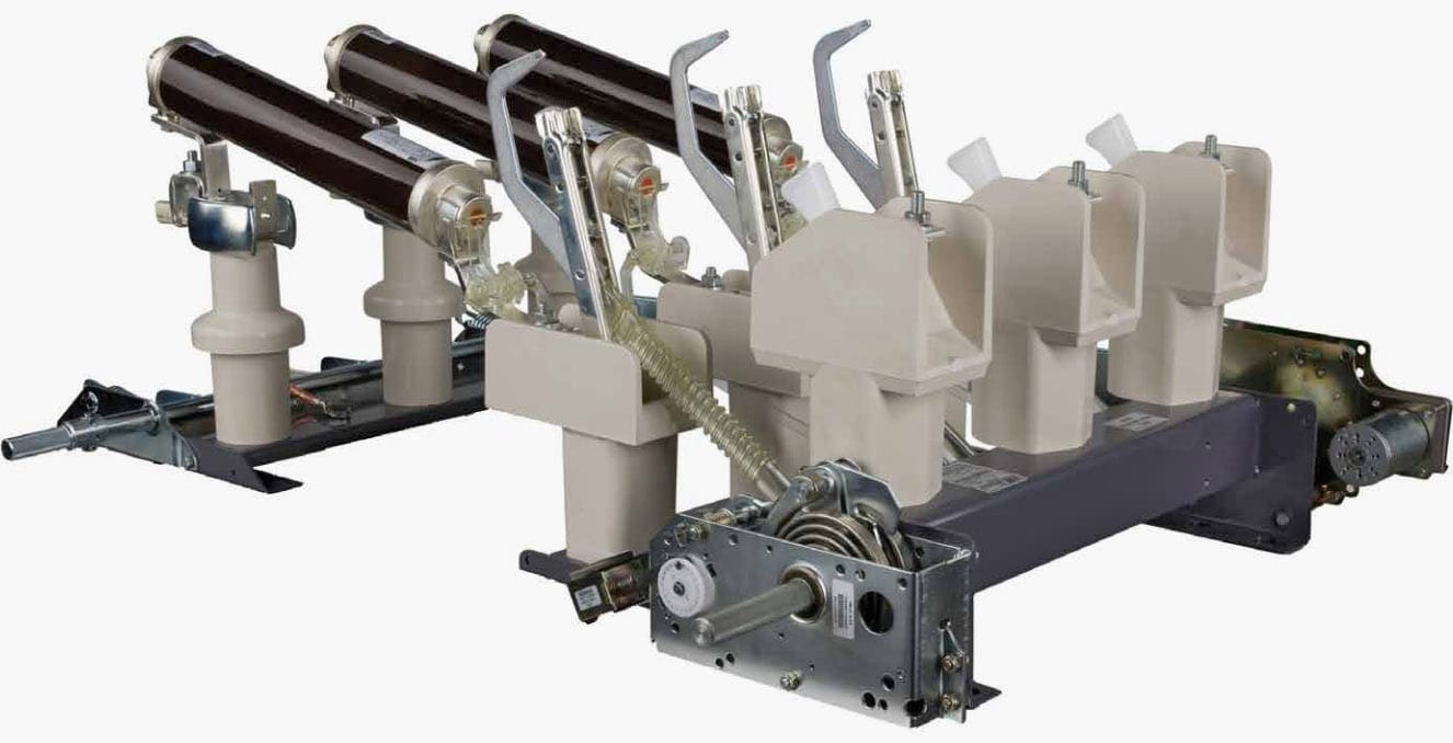
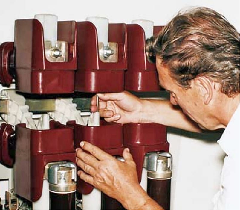
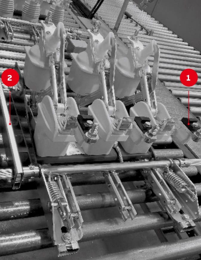
Earthing switches are installed in switchgears primarily near cable sealing ends, i.e. before the main switching device. However, earthing switches are often specified also for busbar earthing, for example in metering panels. It the main switching device is a switch-disconnector, the earthing switch and the switch-disconnector will often be on a common base frame (Figure 4).
Every earthing switch must be capable of conducting its rated short-time current without damage.


“Make-proof” earthing switches are also capable of making the associated peak current at rated voltage. For safety reasons, make-proof earthing switches are recommended with air-insulated switchgear because of possible faulty actuations.
In gas-insulated switchgear (GIS), the earthing of a feeder is often prepared by the earthing switch and completed by closing the circuit-breaker. In this case, a separate make-proof earthing switch is not required.
3.1 Recognizable switch position
Because disconnectors, switch-disconnectors and earthing switches are very important to safety in the isolation of cables, lines and station components, there are special requirements for their position indication.
It is true that the switch contacts themselves no longer need to be directly visible, but it is required that the switch position be recognizable, i.e. that actuation of indicators or auxiliary switches must be picked up directly at the switch contacts and not from a link in the tome transmission mechanism upstream from the operating spring (IEC 62271-102 ).
4. HRC fuse links
The load current flows in fuse links through narrow melt-out conductor bands, which are arranged spirally in a sealed dry quartz sand filling in the interior of an extremely thermally resistant ceramic pipe. The conductor bands are designed with a narrower cross-section at many points to ensure that in the event of an overcurrent or short-circuit current, a defined melting will occur at many points simultaneously.
The resulting arc voltage ensures current limiting interruption in case of high short-circuit currents.


The cap-shaped end contacts of the HRC fuse link are picked up by the terminal contacts of the fuse base. HRC fuse links can be fitted with indicators or striker pins, which respond when the band-shaped conductors melt through.
The striker pin is required for mechanical tripping of the switching device when used in the switch/fuse combination.
4.1 Characteristic current values for HRC fuse links
4.1.1 Rated current
The majority of fuse links in operation have a rated current < 100 A. For special applications with smaller service voltages (e.g. 12 kV), fuse links up to 315 A are available. The associated melt-through times of the fusible conductors can be found in the melting characteristics published by the manufacturers (Figure 6).


4.1.2 Rated maximum breaking current
This value must be provided by the manufacturer of the fuse link. ft is influenced by the design for a specified rated current. When selecting fuse links for transformer protection in distribution systems, the maximum breaking current is not a critical quantity.
4.1.3 Rated minimum breaking current
Classification of fuse links into three categories:
- Back-up /uses – Smallest breaking current (manufacturers information) in general at 2.5 to 3.5 times rated current. Suitable for application in switch/fuse combinations. Very common!
- General purpose fuses – The smallest breaking current is that which results in melt-through after 1 hour or more of exposure time (generally twice the rated currant).
- Full-range fuses – Every current that results in a melt-through can be interrupted.
4.1.4 Cut-of current characteristic
The maximum value of the current let-through by the fuse depends on its rated current and the prospective short-circuit current of the system at the point of installation.
Figure 7 shows a characteristic field.


4.2 Selecting fuse links for specific conditions
When protecting transformers and capacitors with fuses, the inrush currents must be taken into account. When protecting transformers, selectivity is required by making the melting gmes of low-voltage fuses and HRC fuses match to ensure that the low-voltage fuses respond first.
When selecting fuse links for protection of high-voltage motors, the starting current and the starting time of the motors must be taken into account.
The frequency of start-ups must also not be neglected, if this is frequent enough to prevent the fuses from cooling down between starts.
5. Short-circuit current limiter
The increasing requirements for energy throughout the world demand higher rated or supplementary transformers and generators and tighter integration of the supply systems. This can also result in the permissible short-circuit currents of the equipment being exceeded and the equipment being dynamically or thermally destroyed.
It is often not technically possible or not economical for the user to replace switchgear and cable connections with new equipment with increased short-circuit current capability.


The implementation of short-circuit current limiter when expanding existing installations and constructing new installations reduces the possible short-circuit current and costs. A circuit-breaker does not provide protection against impermissibly high peak short-circuit currents, because it trips too slowly.
Only the short-circuit current limiter is capable of detecting and limiting a short-circuit current in the initial rise, i.e. in less than one millisecond. The maximum instantaneous current value that occurs remains well below the peak value of the short-circuit current of the system.
The short-circuit current through the limiter is limited so quickly that it does not contribute in any way to the peak value of the short-circuit current at the fault location.


Depending on the voltage, the rated currents of short-circuit current limiter inserts range up to 4,000 A (and even up to 4,500 A at 0.75 kV) and they can be connected in parallel for higher current levels.
Short-circuit current limiters are most commonly used (see Figure 10):
- In couplings,
- In connections between the public network and internal power supply systems
- In parallel with reactors, (avoidance of copper losses and voltage drops at reactors)
- In transformer or generator feeders, and – in outgoing feeder panels.
Depending on the voltage, the rated currents of short-circuit current limiter inserts range up to 4,000 A (and even up to 4,500 A at 0.75 kV) and they can be connected in parallel for higher current levels.


6. Circuit breakers
There are still a number of “small-oil-volume” circuit-beakers in use for rated voltages up to 52 kV in systems, but for new installations only vacuum or SF6 circuit-breakers are used. Circuit-breakers can be stationary mounted or integrated into the panel in withdrawable unit design with appropriate interlocking mechanisms.
Circuit-breakers must be capable of making and breaking all short-circuit and service currents occurring at the operational site.
6.1 Vacuum circuit breakers
Vacuum circuit-breakers are available from the range for short-circuit breaking currents up to 63 kA with rated currents usually from 400 to 4,000 A. For example, the ABB’s VD4 range covers the voltage ranges of 12 kV, 17.5 kV, 24 kV and 36/40.5 kV.
Figure 11 shows a vacuum circuit-breaker of the ABB’s VD4 type in column design.


The components of the main current path (upper breaker terminal, vacuum interrupter, lower terminal, etc.) are embedded in cast resin and thus completely enclosed by insulating material.
The contacts are a copper/chromium composite material, a copper base containing evenly distributed fine-grained chromium particles, which has a good extinguishing and am-resistant response when switching short-circuit currents, and is also distinguished by low-chopping current values when breaking small inductive currents.
6.1.1 Switching overvoltages
Switching overvoltages when switching inductive loads with vacuum circuit-breakers have long been a subject of discussion. The introduction of copper/chromium as the contact material has significantly reduced the occurrence of hazardous overvoltage levels. To cover the residual risk, surge arresters based on metal oxide (MO) are recommended for certain applications.
Examples of such applications are:
- Small motors (with starting current below about 600 A),
- Small generators,
- Reactor coils for power factor correction,
- Dry-type transformers in industrial applications
Only in special cases (e.g. furnace transformers) are supplementary RC circuits required, preferably in the form of ZORC combinations (Zinc Oxide + R + C).
The movable contacts here are actuated by a permanent magnet mechanism with two stable limit positions. The contact movements are initiated by current pulses to one coil for each contact (approx. 100 Watt / 45 ms), generated by discharge of a capacitor, i.e. with less energy than with the magnetic releases of the stored-energy spring mechanism.


Where:
A – Open/closed auxiliary contacts
B – Geared motor for loading closing spring
C – Built-in closing spring loading lever
D – Mechanical signaling device for circuit breaker open/closed
E – Mechanical operation counter
F – Contacts for signaling spring loaded/discharged
G – Signaling device for closing springs loaded/discharged
H – Service releases
I – Closing push-button
L – Opening push-button
M – Operating mechanism locking electromagnet
N – Additional shunt opening release
O – Transient contact
P – Lock that prevents racking-in when door is open
The release currents are exclusively controlled by electronic components (thyristors and transistors). A fixed-programmed logic circuit coordinates the processes and interlock conditions. The contact position is detected by sensors. The interface to the automation system is through binary inputs and outputs.
The pole section with the vacuum interrupter moulded in epoxy resin has optimum dielectric properties, permanent protection against external influences of all types and because of the small number of parts, very little likelihood of faults occurring. This eliminates the requirement for maintenance of this switching device under standard operating conditions.
6.2 SF6 circuit breakers
After its successful implementation in the range of transmission voltages, SF6 has also become established in the medium voltage range. The puffer type arc-quenching principle, which was introduced first, provides an effective arc-quenching gas flow by a mechanically driven piston.
However, this requires high energy driving systems. Hence self-blast am-quenching systems of different types were developed, where the relative movement between the gas and the arc is provided by the am itself.
The arc-quenching system applies the gas compressed in the lower chamber to interrupt small currents with overvoltage factors < 2.5 p.u. even in the case of small inductive currents. High short-circuit currents era interrupted by the self-blast effect applying the pressure built up in the moving chamber by the arc energy.
7. Vacuum contactors
Vacuum contactors, in connection with HRC fuses, are particularly suitable for operational switching of motors with very high switching frequency, e.g. medium voltage motors for pumps, fans, compensators and capacitors. HRC fuses provide protection for cables and circuit components in case of a short circuit.
For example, the vacuum contactors of ABB’s type VSC (see Figure 13) have rated voltages of 3.6 to 12 kV and a rated current of 400 A. and are suitable for switching of motors with ratings of 1,500 (3.6 kV) to 5,000 kW (12 kV), and capacitors from 1,500 to 4,800 kVAr.
This does not however take account of whether suitable fuses are available to take advantage of the listed performance anges.


Sourses:
- ABB guides
- VD4 Medium voltage vacuum circuit breakers 12…40.5 kV – 630…4000 A – 16…63 kA
- V-Contact VSC Medium voltage vacuum contactors
- Indoor Air Switch-disconnector, NAL/NALF/VR Installation and operating instructions 4.16 … 38 kV / 200…1250 A
- UniGear ZS1 Medium-voltage air-insulated switchgear up to 24 kV
i have Question a bout Assembly sf6 fuseness .and fuse less.and the last earthing swich can you help me about that how can Assemmbly
I am just learning to understand more how MV switchgears are built and how will they operate after complete installation.
Having known of 11kV magnetic field minimum clearances,(distance between live contact parts to any metallic of the switch gear frame or phase to phase of live parts), I am just wondering were all these contact live parts be insulated as well just to avoid flush overs and possible inductions?
Pls refer to photo of what I meant.