
Estimated Study Time: 17 minutes
Demands made on MV circuit breakers
The demands made on MV power systems, irrespective of the place of use of the circuit breakers, vary widely in nature. All these functions cannot obviously be performed with the same efficiency.
 Four crucial switching functions of a MV circuit breaker (Facts You MUST Know)
Thus, finally any circuit breaker design can only be a compromise. The main function of circuit breakers is to interrupt short-circuit currents and protect their loads against the effect of such faults.
This function must be carried out with a high degree of safety and reliability.
Switching Functions
In an MV power system, apart from the normal ON/OFF operations, the switching operations can be divided into the following:
1. Short-circuit interruptions
All circuit breakers are designed to interrupt rated short-circuit currents. The number of short-circuit interruptions seen in the life of a circuit breaker depends on its location in the system, quality of the system design, environmental conditions, etc.
In countries like India, where most of the distribution is by means of overhead lines (except in the case of large urban cities where underground cable networks are used), the distribution switchgear is subjected to a large number of short-circuit interruptions.
This is due to bird hits, snapping of lines, thunderstorms, etc.
The other important criterion to be considered in distribution through overhead lines is the auto-reclosing feature required due to the transient nature of the faults.
The VCBs are ideally suited for auto-reclosing duties because they act fast and can be reclosed with a minimum time interval between two closings as cooling of the dielectric is not involved.
Most of the substations in rural areas are outdoor and situated in far-off places. This necessitates the setting up of outdoor maintenance-free circuit breakers.
Porcelain-clad vacuum circuit breakers meet this demand reliably as against the conventional indoor bulk oil circuit breakers used in outdoor kiosks.
Moreover, the availability of vacuum technology for auto-reclosers and sectionalisers has given birth to highly economical / unattended substations for rural application.
2. Switching of capacitive currents
This includes switching of capacitors, unloaded cables and overhead lines as well as single and parallel capacitor banks. Most of the electricity utilities use capacitors in their systems to improve the power factor and to tackle voltage drops.
Vacuum circuit breakers disconnect these loads safely without re-ignition and thus without the associated overvoltages.
Very low energy loss in the contact gap owing to low arcing during the short pre-arcing time, and flat contact surfaces of vacuum breakers obviate the necessity for additional measures.
VCB’s are suitable for switching in single capacitor bank as well as paralleling of Multi-Capacitor banks at much higher currents and rates of rise than minimum oil circuit breakers and SF6 circuit breakers, without the need for damping reactors.
Synchronous switching devices
These apparatuses are classified by Standard IEC 62271-103 High-voltage switchgear and controlgear – Part 103: Switches for rated voltages above 1 kV up to and including 52 kV, as “special purpose switches” for switching class C2 capacitor banks.
Tests for switching capacitive currents have been conducted in accordance with Standard IEC 62271-100, since the test conditions defined by this Standard are more demanding than IEC 62271-103. These tests are comparable to those required by Standard IEEE C37.09a.
Even though modern circuit breakers are designed to minimize the possibility of multiple electric arc restrikes, the statistical probability of occasional restrikes in the case of frequent switchings of capacitive loads exists.
In practice, the closing and opening operations of the switching apparatus are synchronized so that the contacts make or break in the optimal instant, in relation to the phase angle.
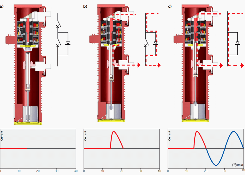
In these cases, many manufacturers has a special switching device and for example ABB has a capacitor switch type ‘DS1’. With reference to figure 1, before the capacitor bank is energized, the apparatus is in situation a), with the switch open and the bank isolated from the grid.
After this, as shown in b), the moving contact connects the diodes and the bank is naturally supplied at voltage zero.
Lastly, as shown in c), after a quarter of a cycle, the moving contact closes the switch and allows current to flow without losses.
3. Switching of inductive currents
The following values are likely to be encountered in various cases of switching inductive currents.
Table 1 – Typical values of inductive current switched by MV switchgear
| Application | Range of Inductive Current |
| Distribution | Very low inductive currents like transformer on no-load up to 20 |
| Industrial Segments | A Low inductive current like compensating reactors up to 2000 |
| Industries/Power Stations | Motors in operation up to 1000 A |
| Motors during starting up to 5000 A |
Vacuum circuit breakers have proved to be adequately suitable for these applications.
3.1 Switching of very low inductive currents
Older vacuum circuit breaker designs had current chopping levels that were as high as 20 A. When these breakers were used to switch transformers, special surge protection devices were required.
Other types of circuit breakers also have high chopping currents of, say, 20 A.
Inductive switching becomes more and more important as a normal duty of medium voltage switchgear. The medium voltage circuit-breakers are in most cases specified and selected according to requirements other than inductive current switching. So far this duty generally represents no difficulties.
In comparison with the circuit-breaker’s rated short-circuit breaking current the inductive breaking current is insignificant.
However the inductive current is usually interrupted before its natural zero by a phenomenon known as current chopping.
Taking into consideration the equivalent inductance and capacitance of the load, an oscillating circuit is acting. The magnetic energy stored in the inductance is transferred at the moment of current chopping as electric energy to the capacitor. Therefore the chopping current creates overvoltages characterized by very steep rates of rise, able to exceed the rise of the withstand voltage of the interrupting unit.
The subsequent multiple re-ignitions and the virtual current chopping phenomenon can reach voltage levels far above the insulation withstand level of the network components.
This is due to capacitive and inductive phase couplings of the overlaid network.

3.2 Switching of low inductive currents
Two main applications fall in this category. These are:
- Switching of compensating reactors and
- Switching of motors under stalled rotor starting conditions.
In these special cases, high overvoltages may occur due to multiple re-ignitions. Vacuum interrupter manufacturers have systematically investigated the switching of motors during starting and made the following observations:
Observation #1
High voltage motors may be safely operated under start-stop conditions by vacuum circuit breakers where surge suppressors are provided to limit associated switching over-voltages.
Observation #2
The front time of the switching impulses is determined by the system configurations mainly by the surge impedance of busbars and cables, and current transformer inductances.
Observation #3
Switching off of motors having starting currents of more than 600 A during starting generates low switching over-voltages and the motors do not require protection by surge suppressors even in 11 kV cable systems.
It has also been observed that when other types of breakers are used to handle such switching operations, high overvoltages may occur due to multiple re-ignition.
Moreover, it has now been found that when motors are switched ‘ON’, high overvoltage surges can occur which are independent of the arc-quenching medium including in SF6 circuit breakers.
Thus, vacuum circuit breakers, which are provided with surge limiters, offer protection to the motor even when it is switched ‘ON’.
4. Special applications
Special applications like arc furnaces involve a large number of operations per day. Track-side sub-stations require the switchgear to operate in varying set of conditions from switching the charging current of catenary systems to transformer magnetising currents to a whole range of load currents and fault currents varying from 2 kA to 12 kA.
These applications also require the switchgear to have the capability to withstand a range of voltages of various waveforms from sinusoidal to steep fronted surges throughout its useful life.
Vacuum circuit breakers have been found to be superior to all conventional and SF6 circuit breakers for such applications.
4.1 Arc Furnace Applications
Electric arc furnaces with ratings up to 100 MVA generally employ special circuit breakers, for which purpose air blast circuit breakers have been used till now.
Normal oil, air and SF6 circuit breakers are found to be unsuitable for this application. Special air circuit breakers are very expensive due to stringent requirements for relatively small quantities.
The standard vacuum circuit breaker offers an economical and reliable solution for this application.
4.2 Use in Traction System
The system used for electric traction generally has voltages between 15 and 25 kV and frequency of 16-2/3, 50 and 60 Hz. The main function of the single-phase traction circuit breakers is quick interruption of short-circuits on the overhead catenary system, which occur frequently and are usually transient in nature.
Since VCBs have short contact travel and shorter arcing times, the total break time is quite less and thus meets the special requirements of short breaking times easily.
The number of short-circuits occurring on an overhead catenary system is much higher than those occurring on transmission lines.
Thus the higher permissible cumulative current of vacuum circuit breakers, i.e. up to 100 operations at rated short-circuit current or 30,000 operations at rated normal current, makes them especially suitable for this application.
4.3 Use on Ships
Circuit breakers meant for use on ships have to fulfill the following special requirements:
- They must remain operational even in an inclined position; and
- Circuit breakers used on ships are subjected to vibrations in actual use.
Circuit breaker manufacturers are able to comply with these requirements more easily in the case of vacuum circuit breakers.
References //
- Switchgears book by BHEL – Bharat Heavy Electricals Limited
- SWITCHING OF SMALL INDUCTIVE CURRENTS USING VACUUM CIRCUITBREAKERS by Pavel NOVAK, Mario HAIM, Peter BEER, Uwe KALTENBORN and Stephane MELQUIOND (Schneider Electric)
- IEC: 62271-100, “High Voltage Alternating Current Circuit Breakers”
- IEC: 62271-200, “Metal Enclosed Smitchgear and Control Gear for Rated Voltage upto and including 38kV”
- Medium voltage switching devices: technologies and applications by ABB
Related electrical guides & articles


Edvard Csanyi
Hi, I'm an electrical engineer, programmer and founder of EEP - Electrical Engineering Portal. I worked twelve years at Schneider Electric in the position of technical support for low- and medium-voltage projects and the design of busbar trunking systems.I'm highly specialized in the design of LV/MV switchgear and low-voltage, high-power busbar trunking (<6300A) in substations, commercial buildings and industry facilities. I'm also a professional in AutoCAD programming.
Profile: Edvard Csanyi

Well explained .thank you.
Very nice information and very useful for users of this type of MV switchgear
Very good Valuable Topic!!
Hello,
I would like to thank you for your useful subject.