
Estimated Study Time: 37 minutes
Design of a 220/33 kV switchyard
This technical article continues with the switchyard design series by studying the case of the 220/33 kV 200 MW wind farm switchyard in which the design steps are put into practice. Previously, a switchyard design methodology was addressed and it’s advisable to read it first. There are many different ways in which a switchyard can be designed. Each way would have some advantages and disadvantages.
 The art of the switchyard design: Case study of a 220/33 kV 200 MW wind farm
This methodology is a structure that follows the work of the switchyard’s experts for many decades. Groundworks represent the first stage, where basic engineering works are settled. This includes the voltage selection, grid substation through which the power is transmitted to the network, and the factors for selecting the substation location are elaborated.
The underlying project delivery method determines the extent to which an organization details the design. If an organization decides on tendering the design (design-bid-build), this stage is enough.
If the organization, however, is into in-house detailed design, the next phase is the detailed engineering design.
Then, the execution phases come into play in which the plan layout, sectional views, grounding design, cable routes, lightning, and erection key diagrams (clamps & connectors) are all presented. The secondary engineering comes at last, where protection concept, relay settings, protection SLD, cable termination and schedule, and many others are finalized.
- Case Study
- Equipment Sizing
- Switchyard Plan Layout
- Grounding Design
- Lightning Protection
- Control and Protection
1. Case Study
A wind power plant of an installed capacity of 200 MW is to be integrated into the network through a transmission substation (switchyard) that is linked to the network through a selected grid substation. The grid substation is at 220 kV level. The 220 kV level is suitable for the 200 MW output power as per the local guidance that restricts the maximum power for a given voltage level.
Recall the voltage formula given in the previous article:
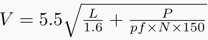
In this formula, L is the line length in kilometres, P is the transmitted power in kW, pf is the power factor, and N is the number of circuits, and the given information is as follows:
- The distance between wind farm and switchyard is 10 km.
- The power is 200 MW.
- The power factor is 0.95.
- The number of circuits is two.
Wind power comprises hub (rotor) blades that are 120 degrees in phase shift. These blades are linked to an induction generator and a step-up transformer contained in a nacelle. The hub and the nacelle are mounted on top of a tower that is in the range of 90-110 meters in height.
The arrangement inside wind powers varies as in Figure 1, where the transformer is located at the bottom of the wind power.
Figure 1 – Wind power connections

In this project, the generation voltage is 690 V that is stepped up to 33 kV, and each wind power generates 2 MW, so the output current is about 37 A. The aggregate output current is 3700 A for the designed capacity of 200 MW.
The wind power industry has an oligopoly market structure in which few firms dominate the industry. Mainly, three organizations exist in this industry: Suzlon, Siemens Gamesa, and Vestas.
The design, execution, and commissioning are out of the scope of the switchyard design office, and what is important is the output cable(s) reaching the transmission substation.
1.1. Preparation of Single-Line Diagram
The very first activity at this stage is to select the number of incoming cables from the wind farm in accordance with two criteria-namely, reliability and conductor size and weight. The IEEE Gold book explains the reliability evaluation procedure required for any study including the configuration of the incoming cables.
Moreover, a designer should consider the amount of power loss whose impact is affordable in case of any cable failure. Different options are listed in Table 1 along with the impact of one incomer failure. It is clear that as the number of incomers lines increase the reliability increases but at a higher cost.
Without going for detailed reliability computations, designers selected the fourth option (10 lines) as the optimal arrangement.
Table 1 – Number of incomers versus power lost
| Number of incomers | Power lost (MW) |
| 1 | 200 |
| 2 | 100 |
| 5 | 40 |
| 10 | 20 |
The conductor size and weight is another determining factor in setting the number of incomer lines. The one incomer option that feeds 3700 A mandates using quad Bersimis conductors that are too heavy for the 33 kV available towers. Similarly, other options do not make any practical feasibility nor economic feasibility except for the last one (i.e. 10 lines).
This selection enables us to go for the Wolf or the Panther conductor size (preferable in 33 kV) in which the gross weight is less than 1 ton/km/tower. Hence, the conductor size and weight go hand in hand with the reliability study for compatibility purposes.
Now, it has been decided to set 10 incoming lines from the wind farm to the switchyard. The number of transformers, as well as the busbar configurations, are to be finalized to complete the general SLD. The number of transformers is settled in a similar fashion to what we did in the number of incoming lines.
The equipment’s maximum size shall be considered at this stage as well. Generally, air-insulated switchgear (AIS) has a maximum current rating of 2500 A that should not be exceeded. The available short circuit capacity is essential in such selection, which is controlled by the transformer impedance. The available short circuit rating for the 33 kV voltage level is set to 25 kA as per local authority.
Therefore, the two 100 MVA 33/220 kV transformers satisfy these factors.
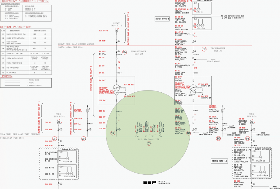
The busbar configuration follows the reliability assessment, but it also abides by common practice. The busbar configuration at 33 kV was a single-busbar with a bus sectionalizer and it was a double-busbar for the 220 kV side.
The switchyard SLD is in Figure 2 illustrates the bus sections with their five incoming lines that feed the 200 MW through the two 100 MVA transformers to the grid substation via the 220 kV busbar two feeders.
Related electrical guides & articles


Salem Alshahrani
Electrical engineer (BEE & Meng). Specialized in substation design, especially in LV/MV switchgears and transformers. Passionate in power system planning, analysis, and stability studies.Profile: Salem Alshahrani
