
Estimated Study Time: 30 minutes
Synchro Check Schemes and Relays
In power systems, synchronization is a fundamental requirement for connecting two sources of electric power, such as a generator to a grid or between segments of the power network. Ensuring that these sources are aligned in frequency, phase sequence, and voltage is critical to maintaining stability and preventing equipment damage.
 Synchro Check Schemes: Key Techniques and Considerations for Power System Stability
This process, known as synchro check, relies on sophisticated schemes and relays that continuously monitor and match these parameters before allowing the connection.
This article provides a comprehensive look into the components and considerations for implementing synchro check schemes in power systems. The article dives into key parameters like frequency and phase shift that impact synchronization. However, I suggest first studying my previous article “Synchronization and Reactive Power Control in Power System“.
By understanding these principles and tools, power engineers can ensure safe and efficient synchronization of power sources, safeguarding both equipment and system reliability.
- Understanding Phase Shift: Implications for Power Source Synchronization
- Frequency Considerations in Power Systems
- Manual Synchronizing Operation
- The Role of Synchronoscopes in Power System Synchronization: Monitoring Phase and Frequency
- Double Frequency Meter
- Manual Synchronization Process
- Manual Synchronization Process Using Double Voltage Meter
- Key Parameters for Effective Synchronization: Insights into REC670 Relay Settings
- Synchro Check Schemes: An Overview of Live and Dead Conditions
- BONUS (PDF) 🔗 Download Safe Work Manual for Power Substations and Switchyards
1. Understanding Phase Shift:
Implications for Power Source Synchronization
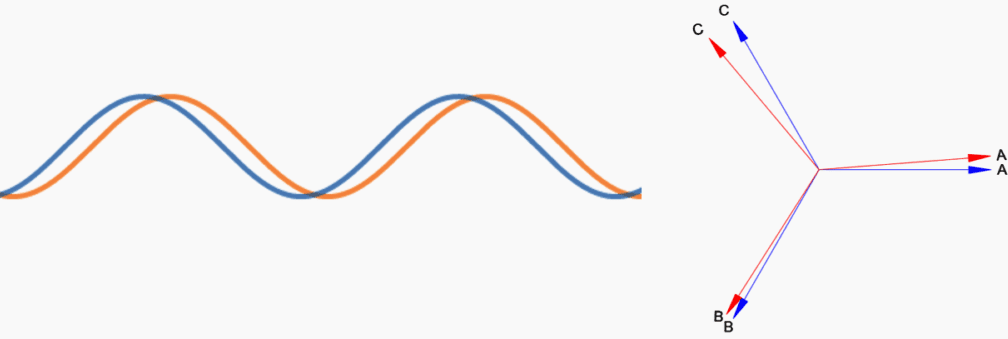
Even when two power sources have the same voltage level and rotational speed, a steady-state phase shift can still exist between them. This phenomenon is illustrated in the figure below, where both waveforms exhibit identical amplitude and frequency but are offset in time, indicating a phase difference.
Phase Shift in Voltage Sources
In an ideal scenario, when paralleling two power sources, the ideal phase shift would be zero. However, achieving this is not typically practical in real-world applications.
The presence of a phase shift between two sources can significantly affect their operation. When the phase angles differ, it leads to the exchange of real power (watts) between the two sources.
This exchange can be quantified using the following equation for real power exchange:
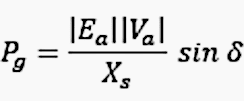
Where:
- Pg = Real power exchanged
- Ea = Voltage of Source 1
- Va = Voltage of Source 2
- Xs = Interconnecting impedance
- δ = Phase angle difference between Ea and Va
When the phase shift between the two sources is zero, there is no real power exchange occurring between them. This condition is ideal since it indicates that all power generated is being delivered to the load rather than circulating between the two sources.
In this situation, the focus is on ensuring that power flows efficiently to the load rather than being exchanged back and forth between the sources.
Figure 1 – Example of phase shift, however frequency and phase sequences are same
2. Frequency Considerations in Power Systems
While most utility power sources maintain stable frequencies of either 60 Hz or 50 Hz, there are instances when one source may have a slightly higher or lower frequency.
This situation often arises when a generating station operates as an islanded source (isolated from the main grid) or when power is supplied by a local standby generator.
Synchronization Challenges
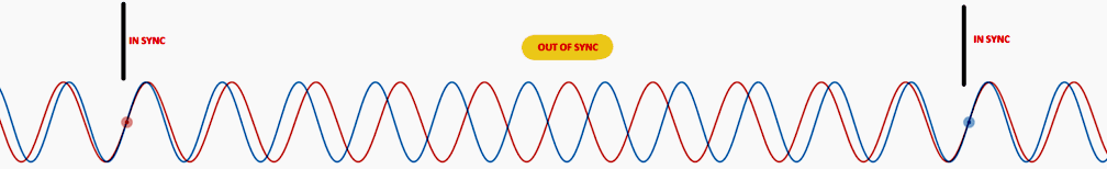
When one power source has a slightly higher frequency, the two sources may achieve perfect synchronization for a moment, only to drift back out of sync shortly thereafter.
This phenomenon can be visualized by examining two waveforms with slightly different frequencies, which illustrate how they can initially align with zero phase angle difference (in sync) and then gradually drift apart (out of sync) over time.
Real Power Flow Dynamics
If two sources with differing frequencies are interconnected, real power (measured in watts) will flow between them. The flow of real power will vary based on the relative phase angle difference between the two waveforms.
Because the frequency—and, consequently, the rotational speed—of one source is slightly ahead, the phase angles continually change, resulting in fluctuating real power exchanges.
Example of Frequency Drift
Consider the scenario in which a utility power source is synchronized with a local diesel generator. The frequency of the generator may exhibit continuous drifting. Consequently, the utility and generator voltages will only align perfectly (synchronize) at certain intervals.
During these moments of synchronization, it is crucial for the circuit breaker to close, ideally utilizing anticipatory phase angle methods that will be discussed later in this article.
When operating in parallel, the generator frequency will closely follow the utility source’s frequency. However, once the two are disconnected, the generator frequency is likely to drift again, necessitating careful monitoring and adjustments to maintain synchronization in future operations.
Figure 2 – The example of frequency drift (click to zoom)
3. Manual Synchronizing Operation
Synchro check operation can be done manually or automatically using synchro check relays. Here we will review how manual operation is done. This is and old method where operator by using three meters check and manually close the circuit breaker.
There synchronous panel consist of synchronoscope, frequency meter and the voltage meter.
4. The Role of Synchronoscopes in Power System Synchronization:
Monitoring Phase and Frequency
A synchronoscope is a vital instrument used in substations and power systems to ensure safe and precise synchronization between two power sources, typically the busbar and the incoming line. The synchronoscope is connected to both the line-side voltage and the bus-side voltage and monitors the phase angle difference and frequency difference between the two sources.
This is typically done when the synchronoscope’s needle is near the centre position, marked by a green area, which indicates that the phase difference is minimal.
Figure 3 – Synchroscope is used to connect two different sources
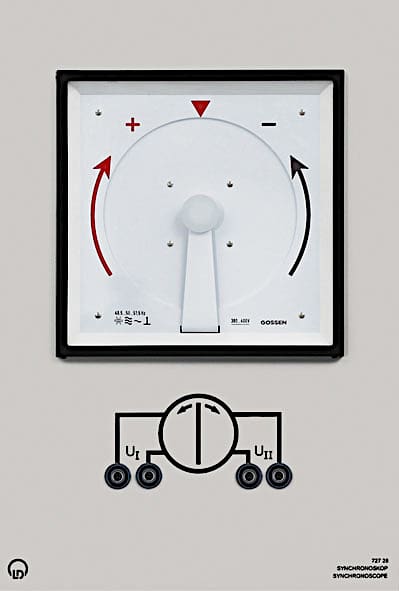
The needle on the synchronoscope continuously rotates, reflecting the phase angle difference. If the phase angle difference between the two sources is large, the needle rotates quickly.
Conversely, if the phase difference is small, the needle moves slowly, giving the operator more time to issue the closing command at the precise moment when the two sources are in sync.
Watch the Video – Generator Synchronization: Theory and Simulation
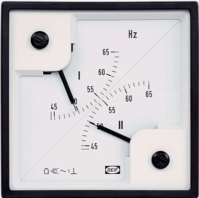
5. Double Frequency Meter
The use of analogue double frequency meters for synchronization was a fundamental practice in earlier power systems, particularly before the advent of digital technologies. These meters were crucial for the manual synchronization of generators with the grid (busbar) or other power sources.
The primary function of a double frequency meter was to display the frequency of two different sources simultaneously — typically, one frequency from the generator and the other from the busbar.
As the generator frequency approached that of the busbar, the vibrating strips would settle, indicating that the two frequencies were nearly synchronized.
Figure 3 – Double Frequency Meter
6. Manual Synchronization Process
Observing the Frequencies: The operator would observe the vibrating strips or other indicators on the analogue double frequency meter. One set of vibrating strips would represent the generator’s frequency, and the other would represent the busbar’s frequency.
Adjusting Generator Frequency:
The operator would adjust the generator’s speed using the governor control to bring the generator’s frequency closer to the busbar’s frequency. This adjustment continued until the vibrating strips of both sources appeared to stabilize, indicating that their frequencies were closely matched.
Related electrical guides & articles


Muhammad Kashif
Muhammad Kashif Shamshad is an Electrical Engineer and has more than 17 years of experience in operation & maintenance, erection, testing project management, consultancy, supervision, and commissioning of Power Plant, GIS, and AIS high voltage substations ranging up to 500 kV HVAC & ±660kV HVDC more than ten years experience is with Siemens Saudi Arabia.Profile: Muhammad Kashif
