
Estimated Study Time: 5 minutes
Synchronizing generator
The physical method
Having discussed the principles of synchronizing the generator to the grid, we will look briefly at the physical method of accomplishing it. In theory, there are at least two simple measurements or indications, which can be used for synchronizing a generator to a grid.
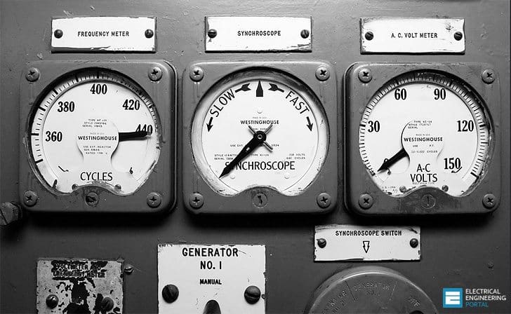 Old generator synchroscope used for matching the speed and phase angle of a generator before connecting it to the power grid (photo credit: Alex Luyckx via Flickr)
When two voltages satisfy the conditions of being equal in magnitude, have the same frequency and an angle of zero between them, then around the voltage loop they add to be zero at each and every instant of time on the sine waves.
Consequently, voltmeters connected across each of the synchronizing breaker contacts will both read zero. Lights placed in the same position will also be totally out when all the synchronizing conditions are satisfied.
The instrument, which will provide this information, is the synchroscope. Figure 1 shows the connection of a synchroscope between the generator being synchronized and the grid.

We will still need to use two voltmeters to check that the generator and the grid voltage are the same (noting that these two voltmeters are not the ones referred to above, since those ones were placed across the synchronizing breaker contacts).
The position of the synchroscope pointer indicates the difference in angle between the generator voltage and the grid voltage. When there is a zero angle between the two voltages, the synchroscope pointer is in the vertical or 12 o’clock, position.

The speed of rotation of the pointer indicates the difference in frequency of the two voltages. The pointer will rotate in the Slow or counterclockwise, direction when the generator frequency is below the grid frequency. The pointer will rotate in the Fast or clockwise, direction when the generator frequency is greater than the grid frequency.
The last two paragraphsindicate that when:
- The pointer is vertical or at 12 o’clock,
- The pointer is steady, not rotating; then the two voltages are in phase and the frequencies of the generator and grid are equal.
In practice, the synchronizing breakers are closed when the generator is just slightly fast and at about the 5 minutes to 12 position moving toward 12 o’clock. This allows a little bit of time for closing the synchronizing breakers and it assures that the generator will not act as a motor once the synchronizing breaker is closed.
It is important to check the correct operation of the synchroscope before each synchronizing is attempted.
To do this, the generator is operated at less than synchronous speed and the synchroscope must rotate in a slow direction. Similarly when the generator is operated at a speed greater than synchronous, the synchroscope must rotate in the Fast direction.
Diesel generators synchronizing with mains (VIDEO)
Diesel generators synchronizing with mains on ‘peak lopping mode‘ and on ‘no-break transfer mode‘.
Generator synchronization (VIDEO)
A Cat trying to sync to the utility 11kv network.
Synchronization VEM generator (VIDEO)
Reference // Science and Reactor Fundamentals – Electrical CNSC Technical Training Group
Related electrical guides & articles


Edvard Csanyi
Hi, I'm an electrical engineer, programmer and founder of EEP - Electrical Engineering Portal. I worked twelve years at Schneider Electric in the position of technical support for low- and medium-voltage projects and the design of busbar trunking systems.I'm highly specialized in the design of LV/MV switchgear and low-voltage, high-power busbar trunking (<6300A) in substations, commercial buildings and industry facilities. I'm also a professional in AutoCAD programming.
Profile: Edvard Csanyi

once we close gen CB to the grid, how does the gen start producing current , while they are running on the same speed
at the moment of connecting a generator to the grid, how dose it start producing current
while Fgen=Fgrid Vgen=Vgrid
The gen produces current after the rotor (field) windings have been excited with DC current. Assuming speed of prime mover = constant, then the active power determined by torque control (some governor system). Reactive power is produced by magnetic field control, in other words, by DC excitation current in the rotor of the gen. The intelligent systems control the reactive power using some AVR type of system. Depending on the power factor u require, the AVR makes the current to lag or lead the voltage.
Interesting articles and remind me when synchronizing low-voltage electrical panels using manual synchronization at palm oil mill in Synchronization VEM generator (VIDEO).
Everything explained above tells what should be done when paralleing generator to grid but my question is what parameters of generator are changed to match voltage,phase sequence and specially frequency.. Syncscope will tell frequency is different but how to remove that difference?
what is most important small gennerator with capacitor connaction ?
Similar question to this:
I can see that you may be adjusting the frequency output on your generator via some dial – but how do you ensure the frequency is in phase?
sir we have 80 MW captive power plant. we have GTCB and SENDING breaker (export to grid) in series. and between this we have one tapping to our sister companies. when there is any problem in sending breaker than our plant doesn’t came on home load. our plant was tripped on overfluxing and than it will giving tripped command to turbine and our plant was blackout.
for example if our generation is 70 MW and our sister companies load is 40 MW and we export to grid is 25 MW . due to grid fault if our sending bay breaker open than around 45 MW load available. but within 4 sec our plant tripped on overluxing.
sir can you please give possible reason for that.
Chek CT winding and ratio
The Diesel generators synchronizing with mains video needs better close-ups of what is occurring in the readout displays; captions were appreciated, tho. The second video Generator synchronization was better, but once cannot distinguish what the parameters are on the face plate. Altho wobbly, the Synchronization VEM generator was the best demonstration of synchronization.
I agree Kimberly! I couldn’t find better videos, so choice was these three. I’ll try to digg better videos.
I learn a lot frm these articles…thanks eep…keep doing ur get wrk