
Estimated Study Time: 12 minutes
General
Synchronous motors convert electrical power to mechanical power and synchronous generators convert mechanical power to electrical power; and synchronous condensers supply only reactive power to stabilize system voltages.
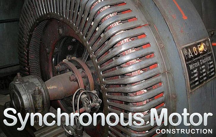
Synchronous motors, generators, and condensers perform similarly, except for a heavy cage winding on the rotor of motors and condensers for self-starting. A rotor has physical magnetic poles, arranged to have alternating north and south poles around the rotor diameter which are excited by electric current, or uses permanent magnets, having the same number of poles as the stator electromagnetic poles.
The stator winding, fed from external AC multi-phase electrical power, creates rotating electromagnetic poles. At speed, rotor poles turn in synchronism with the stator rotating electromagnetic poles, torque being transmitted magnetically across the ‘‘air gap’’ power angle, lagging in generators and leading in motors.
Synchronous machine sizes range from fractional watts, as in servomotors, to 1500 MW, as in large generators. Voltages vary, up to 25,000 V AC stator and 1500 V DC rotor. Installed horizontal or vertical at speed ranges up to 130,000 RPM, normally from 40 RPM (water-wheel generators) to 3600 RPM (turbine generators). Frequency at 60 or 50 Hz mostly, 400 Hz military; however, synthesized variable frequency electrical supplies are increasingly common and provide variable motor speeds to improve process efficiency.
Typical synchronous machinery construction and performance are described; variations may exist on special smaller units.
This technical article is intentionally general in nature. Should the reader want specific application informa-tion, refer to standards: NEMA MG-1; IEEE 115, C50-10 and C50 13; IEC 600034: 1-11, 14-16, 18, 20, 44, 72, and 136, plus other applicable specifications.
Construction
Stator
Frame
The exterior frame, made of steel, either cast or a weldment, supports the laminated stator core and has feet, or flanges, for mounting to the foundation. Frame vibration from core magnetic forcing or rotor unbalance is minimized by resilient mounting the core and=or by designing to avoid frame resonance with forcing frequencies. If bracket type bearings are employed, the frame must support the bearings, oil seals, and gas seals when cooled with hydrogen or gas other than air. The frame also provides protection from the elements and channels cooling air, or gas, into and out of the core, stator windings, and rotor.
Where cooling water is unavailable and outside air cannot circulate through the frame because of its dirty or toxic condition, large air-to-air heat exchangers are employed, the outside air being forced through the cooler by an externally shaft-mounted blower.
Stator Core Assembly
The stator core assembly of a synchronous machine is almost identical to that of an induction motor. A major component of the stator core assembly is the core itself, providing a high permeability path for magnetism. The stator core is comprised of thin silicon steel laminations and insulated by a surface coating minimizing eddy current and hysteresis losses generated by alternating magnetism.
The laminations are stacked as full rings or segments, in accurate alignment, either in a fixture or in the stator frame, having ventilation spacers inserted periodically along the core length. The completed core is compressed and clamped axially to about 10 kg/cm2 using end fingers and heavy clamping plates.
Core end heating from stray magnetism is minimized, especially on larger machines, by using non-magnetic materials at the core end or by installing a flux shield of either tapered laminations or copper shielding.

A second major component is the stator winding made up of insulated coils placed in axial slots of the stator core inside diameter. The coil make-up, pitch, and connections are designed to produce rotating stator electromagnetic poles in synchronism with the rotor magnetic poles.
The stator coils are retained into the slots by slot wedges driven into grooves in the top of the stator slots. Coil end windings are bound together and to core-end support brackets.
If the synchronous machine is a generator, the rotating rotor pole magnetism generates voltage in the stator winding which delivers power to an electric load. If the synchronous machine is a motor, its electrically powered stator winding generates rotating electromagnetic poles and the attraction of the rotor magnets, operating in synchronism, produces torque and delivery of mechanical power to the drive shaft.
Rotor
The Rotor Assembly

The rotor of a synchronous machine is a highly engineered unitized assembly capable of rotating satisfactorily at synchronous speed continuously according to standards or as necessary for the appli-cation. The central element is the shaft, having journals to support the rotor assembly in bearings.
Located at the rotor assembly axial mid-section is the rotor core embodying magnetic poles. When the rotor is round it is called ‘‘non-salient pole’’, or turbine generator type construction and when the rotor has protruding pole assemblies, it is called ‘‘salient pole’’ construction.
The non-salient pole construction, used mainly on turbine generators (and also as wind tunnel fan drive motors), has two or four magnetic poles created by direct current in coils located in slots at the rotor outside diameter. Coils are restrained in the slots by slot wedges and at the ends by retaining rings on large high-speed rotors, and fiberglass tape on other units where stresses permit. This construction is not suited for use on a motor requiring self-starting as the rotor surface, wedges, and retaining rings overheat and melt from high currents of self-starting.
A single piece forging is sometimes used on salient pole machines, usually with four or six poles. Salient poles can also be integral with the rotor lamination and can be mounted directly to the shaft or fastened to an intermediate rotor spider. Each distinct pole has an exciting coil around it carrying excitation current or else it employs permanent magnets. In a generator, a moderate cage winding in the face of the rotor poles, usually with pole-to-pole connections, is employed to dampen shaft torsional oscillation and to suppress harmonic variation in the magnetic waveform.
Direct current excites the rotor windings of salient, and non-salient pole motors and generators, except when permanent magnets are employed. The excitation current is supplied to the rotor from either an external DC supply through collector rings or a shaft-mounted brushless exciter. Positive and negative polarity bus bars or cables pass along and through the shaft as required to supply excitation current to the windings of the field poles.
When supplied through collector rings, the DC current could come from a shaft-driven DC or AC exciter rectified output, from an AC-DC motor-generator set, or from plant power. DC current supplied by a shaft-mounted AC generator is rectified by a shaft-mounted rectifier assembly.
As a generator, excitation current level is controlled by the voltage regulator. As a motor, excitation current is either set at a fixed value, or is controlled to regulate power factor, motor current, or system stability. In addition, the rotor also has shaft-mounted fans or blowers for cooling and heat removal from the unit plus provision for making balance weight additions or corrections.
Bearings and Couplings
Bearings on synchronous machinery are anti-friction, grease, or oil-lubricated on smaller machines, journal type oil-lubricated on large machines, and tilt-pad type on more sophisticated machines, especially where rotor dynamics are critical. Successful performance of magnetic bearings, proving to be successful on turbo-machinery, may also come to be used on synchronous machinery as well.
As with bearings on all large electrical machinery, precautions are taken with synchronous machines to prevent bearing damage from stray electrical shaft currents. An elementary measure is the application of insulation on the outboard bearing, if a single-shaft end unit, and on both bearing and coupling at the same shaft end for double-shaft end drive units.
Damage can occur to bearings even with properly applied insulation, when solid-state controllers of variable frequency drives, or excitation, cause currents at high frequencies to pass through the bearing insulation as if it were a capacitor. Shaft grounding and shaft voltage and grounding current monitoring can be employed to predict and prevent bearing and other problems.
Related electrical guides & articles


Edvard Csanyi
Hi, I'm an electrical engineer, programmer and founder of EEP - Electrical Engineering Portal. I worked twelve years at Schneider Electric in the position of technical support for low- and medium-voltage projects and the design of busbar trunking systems.I'm highly specialized in the design of LV/MV switchgear and low-voltage, high-power busbar trunking (<6300A) in substations, commercial buildings and industry facilities. I'm also a professional in AutoCAD programming.
Profile: Edvard Csanyi

Excellent web site
OPPS!! SOMEONE FORGOT TO MENTION THERE IS A CLASS OF BRUSHLESS SYNCHRONOUS MOTORS LIKE THE ONES USED IN THE BASEMENT OF THE WORLD TRADE WHEN IT WAS BUILT!!
THERE WERE SEVEN (7) 7000HP BRUSHLESS SYNCHRONOUS 1200RPM, 13.2KV MOTORS THAT
POWERED THE AIR CONDITIONING COMPRESSORS IN THE 5TH SUB-BASEMENT. SERIAL NUMBERS
68-1441-ETC
Excellent Web site
Excellent Web site , really useful.
Nice article.
Any information on damper bars or windings in synchronous machines would also be great.