
Estimated Study Time: 13 minutes
Construction
Like the asynchronous motor, the synchronous motor consists of a stator and a rotor separated by the air gap. It differs from the asynchronous motor in that the flux in the air gap is not due to a component of the stator current.
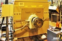
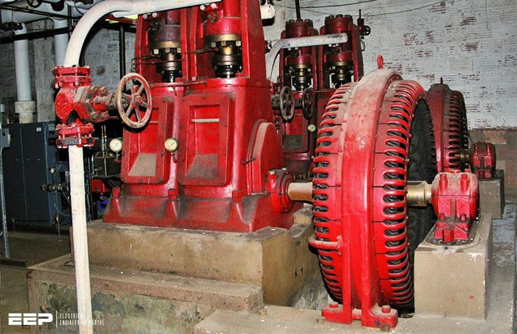 A pair of ancient Carbon Dioxide air conditioning compressors, powered by two antique 150 horsepower open frame synchronous motors. This type of A/C system dates to the 1930's. (photo credit: Jeffs4653 via Flickr)
It’s created by magnets or by the field coil current provided by an external DC source energizing a winding placed in the rotor.
Let’s see the topics we will discuss.
Stator
The stator consists of a housing and a magnetic circuit generally comprising silicon steel laminations and a 3-phase coil similar to that of an asynchronous motor supplied with 3-phase AC to produce a rotating field.

Rotor
The rotor carries field magnets or coils through which a direct current flows and which create interposed North and South poles. Unlike asynchronous machines, the rotor rotates with no slip at the speed of the rotating field.
There are therefore two different types of synchronous motor: magnet motors and wound rotor motors.
With permanent magnets
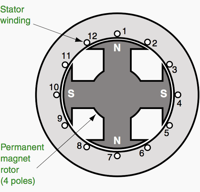
With magnet motors, the motor rotor is fitted with permanent magnets (see Figure 2) (generally rare earth magnets), in order to achieve increased field strength in a small volume. The stator has three-phase windings.
These motors can tolerate significant overload currents in order to achieve high-speed acceleration.
They are always used with a variable speed drive, and these motor-drive assemblies are intended for specific markets such as robots or machine tools, for which smaller motors, acceleration and passband are essential.
With wound coil
The second type of synchronous machine has a wound coil, and is a reversible machine that can operate as either a generator (alternator) or a motor. For many years these machines have been mainly used as alternators.
The development of direct (cycloconverters) or indirect frequency inverters operating with natural switching due to the ability of synchronous machines to provide reactive power, has enabled the creation of high performance, reliable variable speed electric drives.
These drives are particularly competitive in relation to competitors’ solutions for power ratings over one megawatt.
Although it is possible to find synchronous motors used industrially in power ratings ranging from 150 kW to 5 MW, it is above 5 MW that electric drives using synchronous motors become virtually essential, for the most part combined with variable speed drives.
Operating characteristics
The motor torque of the synchronous machine is proportional to the voltage at its terminals, whereas that of the asynchronous machine is proportional to the square of that voltage. Unlike the asynchronous motor, it can work with a power factor equal to one or very close to it.
The synchronous motor therefore has a number of advantages over the asynchronous motor with regard to its ability to be powered via the constant voltage/frequency line supply:
- The speed of the motor is constant, regardless of the load.
- It can supply reactive power and increase the power factor of an installation.
- It can withstand relatively large voltage drops (around 50% due to its over-excitation properties) without stalling.
However, the synchronous motor supplied directly by the constant voltage/frequency line supply has two disadvantages:
- It has starting difficulties. If the motor is not combined with a variable speed drive, starting must be performed at no-load, either by DOL starting for small motors, or using a starting motor that drives it at a speed close to synchronous speed before direct connection to the line supply.
- It may stall if the resistive torque exceeds its maximum electromagnetic torque. In this case, the entire start process must be repeated.
Other types of synchronous motor
To conclude this overview of industrial motors, we must also mention linear motors, synchronized asynchronous motors and stepper motors.
Linear motors
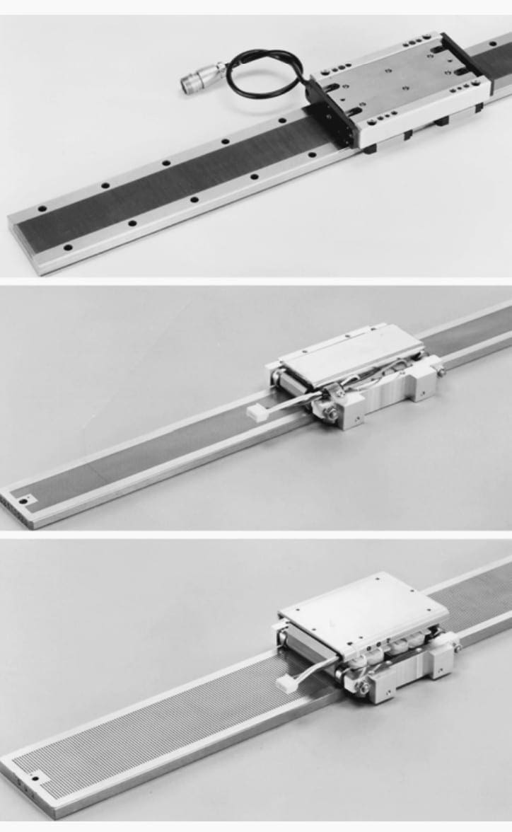
Their structure is identical to that of synchronous rotary motors: they consist of a stator (plate) and a rotor (forcer) which are in line. In general the plate moves along the forcer on a guide. This type of motor does away with all intermediate kinematics for converting the movement, which means there is no play or mechanical wear on this drive.
A linear synchronous motor (LSM) is a linear motor in which the mechanical motion is in synchronism with the magnetic field, i.e., the mechanical speed is the same as the speed of the traveling magnetic field (Figure 3).
The thrust (propulsion force) can be generated as an action of:
- Traveling magnetic field produced by a polyphase winding and an array of magnetic poles N, S,…,N, S or a variable reluctance ferromagnetic rail (LSMs with a.c. armature windings);
- Magnetic field produced by electronically switched d.c. windings and an array of magnetic poles N, S,…,N, S or variable reluctance ferromagnetic rail (linear stepping or switched reluctance motors).
The operation of an LSM does not depend on, which part is movable and which one is stationary.
How does a linear motor work?
Yaskawa Linear Motors in Motion
Synchronized asynchronous motors
These are induction motors. During the starting phase, the motor operates in asynchronous mode and when it has reached a speed close to synchronous speed, it switches to synchronous mode.
If it has a high mechanical load, it can no longer operate in synchronous mode and returns to asynchronous mode. This feature is obtained by special construction of the rotor and is generally for low power motors.
Stepper motors
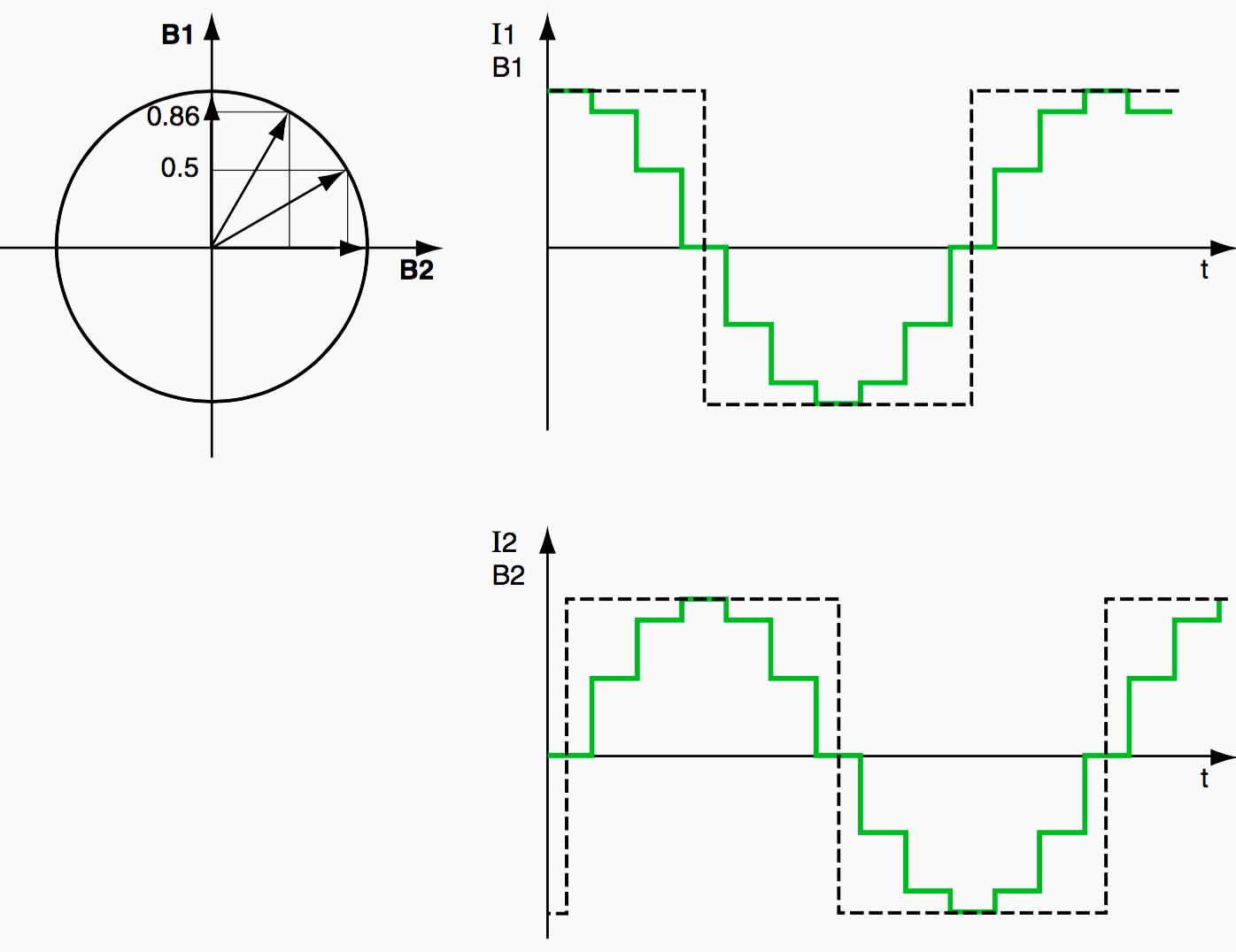
The stepper motor is a motor that operates according to the electrical pulses supplying its coils. Depending on its electrical power supply, it may be:
- Unipolar if its coils are always supplied in the same direction by a single voltage, hence the name unipolar.
- Bipolar when its coils are supplied sometimes in one direction and sometimes in the other. They sometimes create a North pole, and sometimes a South pole, hence the name bipolar.
Stepper motors can be of variable reluctance or magnet type or a combination of the two (see Figure 4).
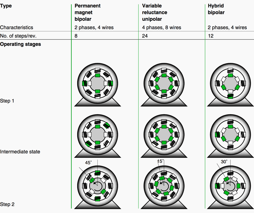
The minimum angle of rotation between two modifications of the electrical pulses is called a step. A motor is characterized by the number of steps per revolution (that is, for 360°). The most common values are 48, 100 or 200 steps per revolution.
The circuits for micro-steps multiply the number of motor steps by 500, thus changing, for example, from 200 to 100,000 steps.
The electronics can be used to control the chronology of these pulses and count the number of pulses. Stepper motors and their control circuits thus enable a shaft to rotate with a high degree of precision in terms of both speed and amplitude.
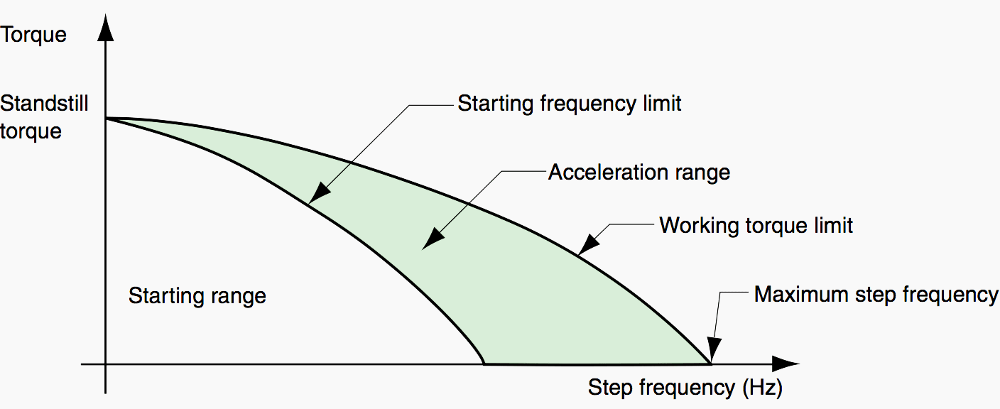
Their operation is thus similar to that of a synchronous motor when the shaft is rotating continuously, which corresponds to specified frequency, torque and driven load inertia limits (see Figure 6). If these limits are exceeded, the motor stalls, the effect of which is to stop the motor.
Accurate angular positioning is possible without a measurement loop. The small models of these motors, generally with power ratings of less than one kW, have a low voltage power supply.
The simplicity of this solution makes it particularly economical (no feedback loop). Magnet stepper motors also have the advantage of a standstill torque when there is no power supply. On the other hand, the initial position of the moving part has to be known and taken into account by the electronics in order to provide effective control.
Stepper Motor Basics – Demo with just Push Buttons!
Arduino Stepper Motor Tutorial!
References:
- Electric motors by E. Gaucheron (Schneider Electric)
- Linear Synchronous Motors by Jacek F. Gieras, Zbigniew J. Piech and Bronislaw Z. Tomczuk
Related electrical guides & articles


Edvard Csanyi
Hi, I'm an electrical engineer, programmer and founder of EEP - Electrical Engineering Portal. I worked twelve years at Schneider Electric in the position of technical support for low- and medium-voltage projects and the design of busbar trunking systems.I'm highly specialized in the design of LV/MV switchgear and low-voltage, high-power busbar trunking (<6300A) in substations, commercial buildings and industry facilities. I'm also a professional in AutoCAD programming.
Profile: Edvard Csanyi

Good article
Very useful and informative guide about Synchronous motors… Thank you….