
Estimated Study Time: 17 minutes
What makes them move? The motor drive.
On the outset, it may be due to wheels as in the case of an automobile. What actually drives these movements, though, are motors. Additionally, many household appliances such refrigerators, air-conditioners, ventilation fans, washers, driers and so many others all require electric motors.
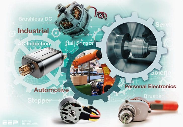 Yup, it's the motor drive that makes systems in motion all around us (photo credit: Texas Instruments)
One can see that motors are part of our day-to-day life. The goal of this technical article is to discuss motor drives and their power electronics – the various components and requirements through applications that we use and encounter in household and industrial environments.
An electric motor is a device that converts electrical energy to mechanical energy. It also can be viewed as a device that transfers energy from an electrical source to a mechanical load. The system in which the motor is located and makes it spin is called the drive, also referred to as the electric drive or motor drive.
Typically, this is the speed of the motor, torque, and the position of the motor shaft. Figure 1 shows the block diagram of a motor drive.
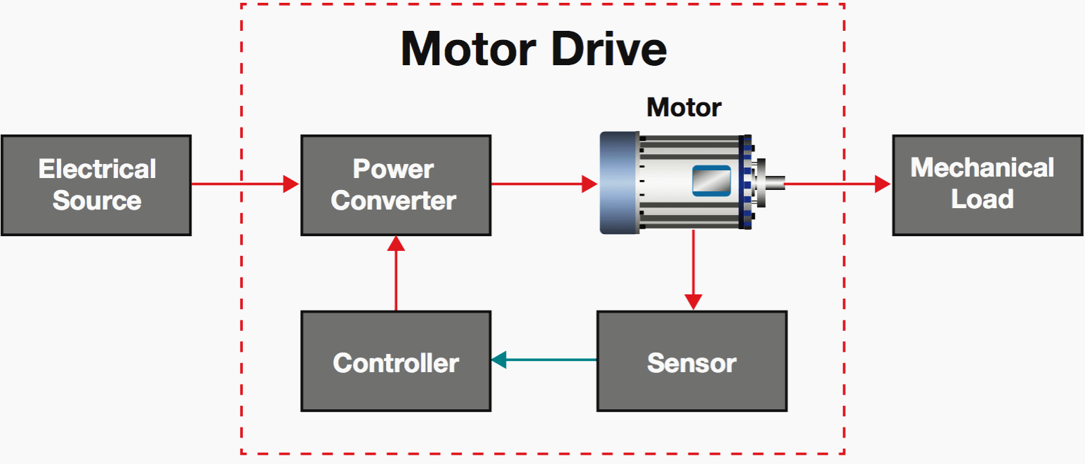
The functions of the power converter circuit in the motor drive are:
- Transfer electrical energy from a source that could be of a given voltage, current at a certain frequency and phase as the input
- To an electrical output of desired voltage, current, frequency and phase to the motor such that the required mechanical output of the motor is achieved to drive the load
- Controller regulates energy ow through feedback coming from the sensor block
- Signals measured by sensors from the motor are low-power, which are then sent to the controller
- Controller tells the converter what it needs to be doing. A closed-loop feedback system is the method of comparing what is actually happening to what the motor should
be outputting, then adjusting the output accordingly to maintain the target output
Motor drive efficiency
Electric motors represent 45 percent of all electrical energy consumption across all applications. Increasing the efficiency of motor-drive systems could potentially result in a significant reduction in global electricity consumption.
With increasing demand of electricity along with industrialization and urbanization across the globe, the ability to supply energy is becoming even more challenging. As part of a global effort to reduce energy consumption and carbon emissions on the environment, various regulations across many countries have put forth and are continually working on governmental mandates to improve motor drive efficiency.
All these requirements make it compelling to have an efficient power converter system using switched-mode power supplies (SMPS). The SMPS uses semiconductor power switches (also called power electronic switches) in a switch mode and on and off states only, that yields 100 percent efficiency in an ideal situation.
Power electronics systems are primarily designed using silicon-based power management with power semiconductor switches. These switches are power MOSFETs, bipolar junction transistors (BJTs), and isolated gate bipolar transistors (IGBTs) that have made significant improvements in their performances. Examples include lower on-state resistance, increased blocking voltage, and higher drive currents.
Furthermore, a lot of development is taking place using wide-band-gap semiconductors such as silicon carbide (SiC). SiC is of particular interest to motor drives that transfer very high power at high- voltage levels.
Motor drive classifications
Before we delve into motor drive applications and the role of power electronics in these systems, here is a quick overview on how motor drives are classified (Figure 2).
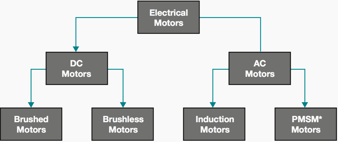
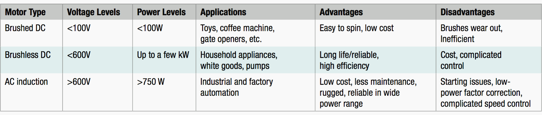
Table 1 summarizes where AC (induction) and DC (brushed and brushless) motors are used in terms of voltage and power levels, along with the pros and cons of each.
Power converter in motor drives
The drive configuration for motors summarized in Table 1 above are generally the same. However, what differs is the power converter topology in the power converter circuit. Since the bulk of these applications are moving towards brushless DC (BLDC) or induction motors, our focus will be on applications that use these two types of motors.
In general, selecting a motor drive may require looking at the power and voltage levels while addressing questions that depend on the application.
Examples could be the starting torque, load inertia, pattern of operation, environmental conditions, or the motor’s ability to regenerate.
AC motor drives
The AC motor drive, as the name suggests, requires an AC input to the induction motor used to drive large industrial loads such as HVAC for commercial buildings – pumps and compressors, factory automation, industrial equipment that requires provisions for speed adjustments such as conveyor belts, tunnel boring, mining, paper mills, and many others.
An AC motor drive takes an AC energy source, rectifies it to a DC bus voltage and, implementing complex control algorithms, inverts the DC back to AC into the motor using complex control algorithms based on load demand.
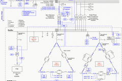
Figure 3 below shows a block diagram of an AC motor drive. The power stage and power supplies are marked in teal.
Power stage
The power converter topology used in the power stage is that of a three-phase inverter which transfers power in the range of kW to MW. Inverters convert DC to AC power. Typical DC bus voltage levels are 600-1200V. Considering the high power and voltage levels, the three-phase inverter uses six isolated gate drivers (Figure 3).
Each phase uses a high-side and low-side insulated gate bipolar transistor (IGBT) switch.
Operating usually in the 20-30 kHz range, each phase applies positive and negative high-voltage DC pulses to the motor windings in an alternating mode.
High-power IGBT requires isolated gate drivers to control their operations. Each IGBT is driven by a single isolated gate driver. The isolation is galvanic between the high-voltage output of the gate driver and the low-voltage control inputs that come from the controller.
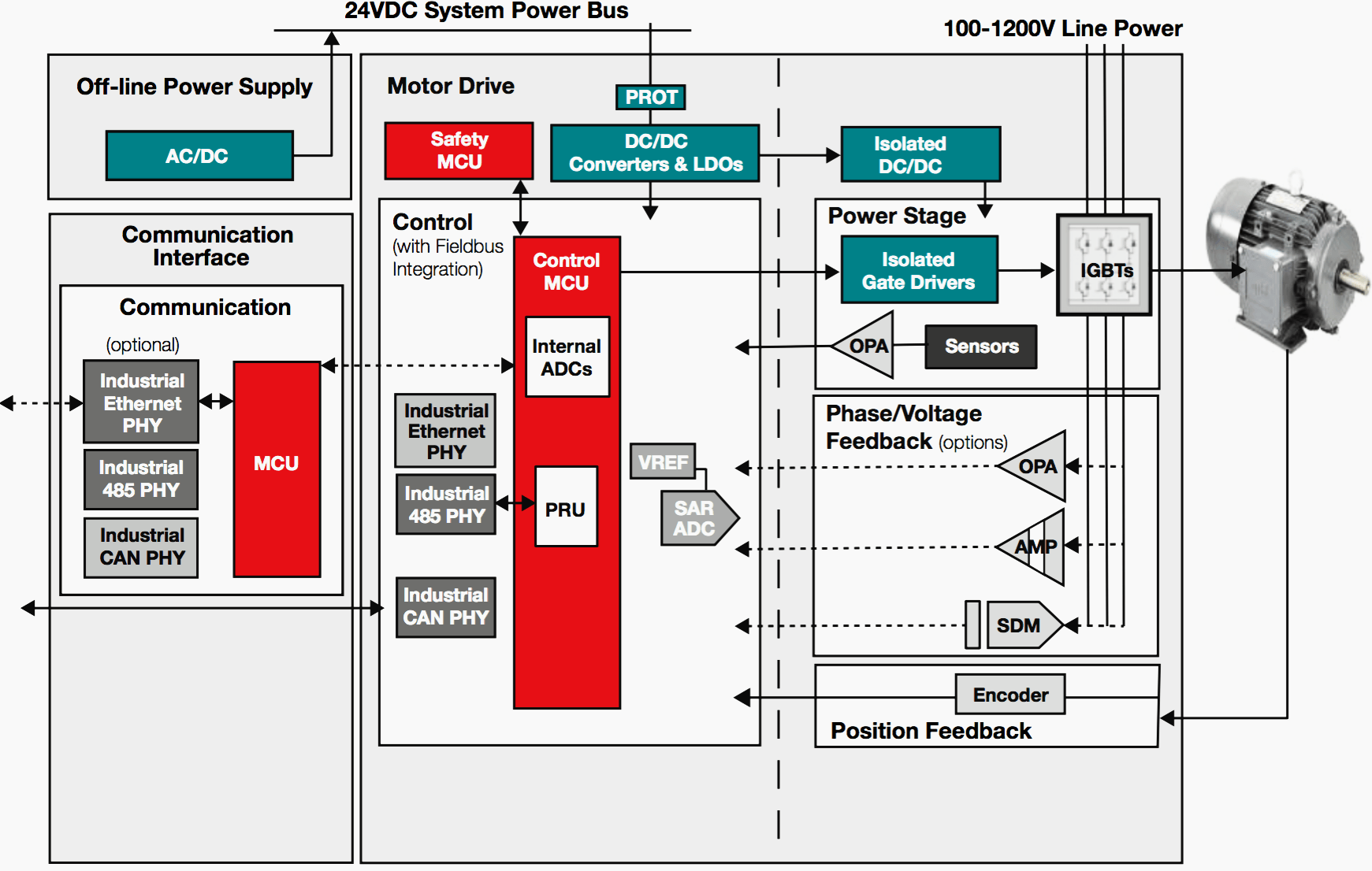
The emitter of the top IGBT floats, which necessitates using an isolated gate-driver. In order to isolate a high-voltage circuit with that of a low- voltage control circuit, isolated gate-drivers are used to control the bottom IGBTs.
Gate drivers convert the pulse-width modulation (PWM) signals from the controller into gate pulses for the FETs or IGBTs. Moreover, these gate drivers need to have integrated protection features such as desaturation, active Miller clamping, soft turn-off and so on.
Figure 4 illustrates this trend.
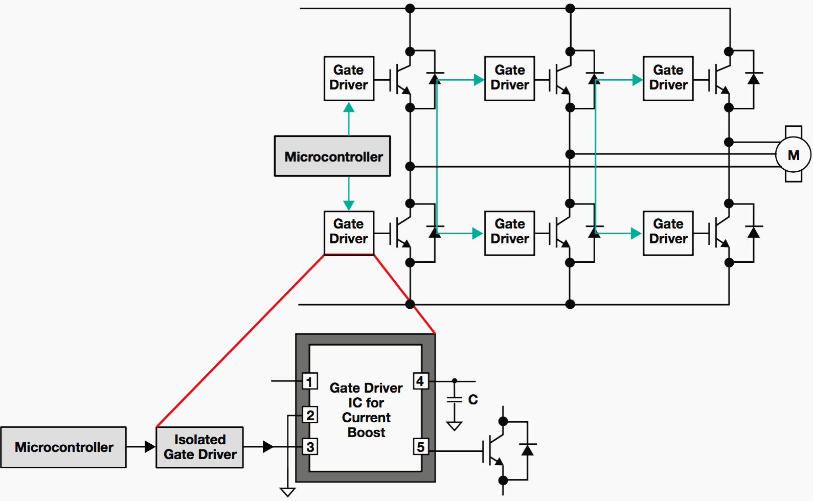
In order to take advantage of the low conduction losses in IGBTs, gate drivers need to operate at voltages much higher than their threshold voltage in the range of 15-18V. Furthermore, an IGBT is a minority-carrier device with high input impedance and large bipolar current-carrying capability. The switching characteristics of an IGBT are similar to that of a power MOSFET.
For a given condition when turned on, the IGBT behaves much like to a power MOSFET, showing similar current rise and voltage fall times. However, the switching current during turn-off is different.
At the end of the switching event, the IGBT has a “tail current” that does not exist for the MOSFET. This tail is caused by minority carriers trapped in the “base” of the bipolar output section of the IGBT. This causes the IGBT to remain turned on.
Unlike a bipolar transistor, it is not possible to extract these carriers to speed up switching, as there is no external connection to the base section. Therefore, the device remains turned on until the carriers recombine. This tail current increases the turn-off loss which requires an increase in the dead time between the conduction of two devices for a given phase of a half-bridge circuit.
Having a negative voltage (–5V to –10V) at the gate helps to reduce the turn-off time by helping to recombine the trapped carriers. When the IGBT is turned on the high dv/dt and parasitic capacitance between gate and emitter generates voltage spikes across the gate terminal. These spikes can cause a false turn-on of the bottom IGBT. Having a negative voltage at the gate helps to avoid this false turn-on trigger.
Usually 15V to 18V is applied to the gate to turn-on the device and a negative voltage of –5V to –8V is applied to turn off the IGBT. This requirement is key to determine the power supply rating to the IGBT driver.
One example of a classic topology used for this power supply is the push-pull isolated converter. This topology is similar to a forward converter with two primary winding. The advantage that push-pull converters have over y-back and forward converters is that they can be scaled up to higher powers, in addition to higher efficiency.
Other power supplies
Figure 3 shows an offline power supply that draws power from the three-phase universal AC line to a regulated 24V DC output. Because of the low-power level (below 75W), power factor correction (PFC) is not needed.
These offline power supplies are typically y-back topology converter ICs that could be a controller with external MOSFET, or an integrated MOSFET controller or switcher.
The 24V DC output is the system power bus in the AC motor drive system that is input into the bias power supply for the power stage and non- isolated DC/DC converter. This non-isolated DC/DC regulator from the 24V system provides power to the controller, communications and safety microcontrollers, interface transceivers, and data converters.
BLDC motor drives
The brushless DC (BLDC) is on trend for becoming the most popular choice, replacing brushed DC and AC motors in markets such as HVAC, especially for its higher efficiency and high reliability. Of particular interest are power tools and household appliances such as refrigerators, air-conditioners, vacuum cleaners and other such white goods.
Using BLDC in these market spaces lowers the system’s overall weight.
Figure 5 shows a block diagram of the BLDC motor drive in a cordless (battery-powered) power tool such as an electric drill. Power blocks are shown in blue.
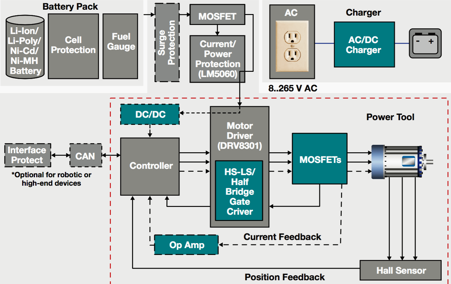
Power stage
A BLDC power stage is also an inverter similar to an AC motor drive, except that the input can be single- or three-phases. DC-rail voltages are typically 48-600V, depending on the power levels. The switch is usually a power MOSFET switching at around 100 kHz. Gate drivers are high-side, low- side or half-bridge drivers per inverter phase with no isolation requirement.
Protection features are not as critical as those needed for the AC motor drive, except for dead-time control to avoid shoot- through since the high-side and low-side drivers are operating from one IC.
Power supplies
Bias power to the controller and gate drivers comes off a regulated power supply from the battery. A typical battery used in this space is the 18V nominal Lithium-Ion (Li-Ion) five-cell battery. Since these are cordless tools, a wall charger is required to charge the drill periodically.
Typically, charging in the range of 50–1000W is done using an isolated controller that is topology-specific, depending on the power level.
Also, PFC is generally not needed unless the power level is in the few hundred W. Typical charging controllers are based off of a y-back, interleaved y-back, or push-pull topologies.
To summarize…
Motor drives are becoming more efficient as power electronic devices such as power switches (IGBTs and MOSFETs), gate drivers and bias supplies are being incorporated. We discussed two key and popular motor drive systems: AC and BLDC, and covered the functionalities and role of gate drive circuits and associated bias supplies.
Key areas such as isolation, voltage levels and protection features were highlighted.
Reference // Power electronics in motor drives: Where is it? by Nagarajan Sridhar (Product Marketing Manager High Performance Isolated Power Solutions Power Management Texas Instruments)
Related electrical guides & articles


Edvard Csanyi
Hi, I'm an electrical engineer, programmer and founder of EEP - Electrical Engineering Portal. I worked twelve years at Schneider Electric in the position of technical support for low- and medium-voltage projects and the design of busbar trunking systems.I'm highly specialized in the design of LV/MV switchgear and low-voltage, high-power busbar trunking (<6300A) in substations, commercial buildings and industry facilities. I'm also a professional in AutoCAD programming.
Profile: Edvard Csanyi
