
T&D pylons and equipment
Recognizing the type of transmission & distribution pylons and their equipment is kind of hard if you don’t know where to look for. There are many variations that look similar and you must have sharp eyes to see the details. This technical article tends to sharpen your eyes.
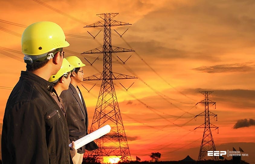 Learn to recognize T&D pylons, foundations, insulators, cables, bushings and arresters
Description of the equipment (line with pylon, cables and substation with transformers, switch yard…) is in the following paragraphs.
1. The structures and pylons
Structures for T&D overhead lines take a variety of shapes depending on the type of line. Structures may be as simple as wood poles directly set in the earth, carrying one or more cross-arm beams to support conductors, or “armless” construction with conductors supported on insulators attached to the side of the pole.
Tubular steel poles are typically used in urban areas. High-voltage lines are often carried on lattice-type steel towers or pylons. For remote areas, aluminium towers may be placed by helicopters.
Concrete poles have also been used. Poles made of reinforced plastics are also available, but their high cost restricts application.
A large transmission line project may have several types of towers, with “tangent” (“suspension” or “line” towers) towers.
These are intended for most positions and more heavily constructed towers used for turning the line through an angle, dead-ending (terminating) a line, or for important river or road crossings.
Depending on the design criteria for a particular line, semi-flexible type structures may rely on the weight of the conductors to be balanced on both sides of each tower.
More rigid structures may be intended to remain standing even if one or more conductors is broken. Such structures may be installed at intervals in power lines to limit the scale of cascading tower failures.
1.1 Type of pylon by function
Anchor pylon
Anchor pylons or strainer pylons are employed at branch points as branch pylons and must occur at a maximum interval of 5 km, due to technical limitations on conductor length.
Branch pylon
Branch pylon is a pylon that is used to start a line branch. The branch pylon is responsible for holding up both the main-line and the start of the branch line, and must be structured so as to resist forces from both lines.
Tension tower
A tension tower with phase transposition of a traction current line for single phase AC 110 kV, 16.67 Hz.
1.2 Type of pylon by material used
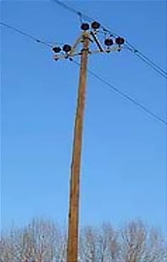
Wood pylons
For support pylons a straight trunk impregnated with tar is usually used, which carries one or more cross beams with the conductor cables on the top.
In Germany wood pylons are used as a rule only for lines with voltages up to approximately 30 kV, while in the U.S. wood pylons are used for lines with voltages up to 345 kV.
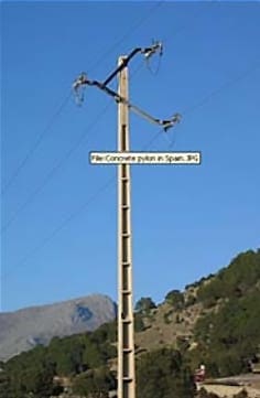
Concrete pylon
Concrete pylon or concrete pole, is an electricity pylon made from reinforced concrete. Concrete pylons are manufactured at the factory and put up at the power line’s right of way. Concrete pylons, which are not prefabricated, are also used for constructions taller than 60 meters.
Such pylons look like industrial chimneys and some of these structures are also used as chimneys. In China some tall pylons of power line crossings of wide rivers were built of concrete.
The tallest of these pylons belong to the Yangtze Power line crossing at Nanjing with a height of 257 meters!
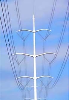
Steel tube pylon
Steel tube pylon is a pylon, which is manufactured from a steel tube. This type of pylon is generally assembled at the factory and set up on the power line’s right of way with a crane.
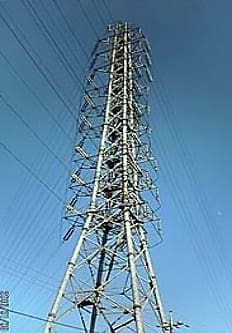
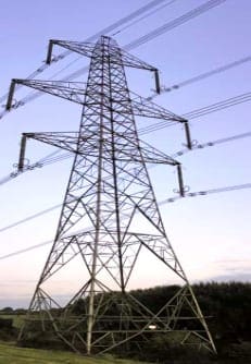
Lattice steel pylon
A lattice steel pylon is an electricity pylon consisting of a steel framework construction. Lattice steel pylons are used for power lines of all voltages.
For lines with operating voltages over 50kV, lattice steel pylons are the form of pylon used most often. Lattice steel pylon is usually assembled from individual parts at the place where it is to be erected.
This makes very high pylons possible (generally up to 100 meters — in special cases even higher).
2. Conductor arrangements
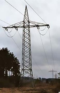
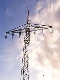
Single-level
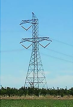
Two-level pylon
Two-level pylon is a pylon at which the circuits are arranged in two levels on two crossbars.
Two-level pylons are usually designed to carry on the lowest crossbar four and at the upper crossbar two conductors, but there are also other variants, e.g. such carrying six conductors in each level or two conductors on the lowest and four on the upper crossbar.
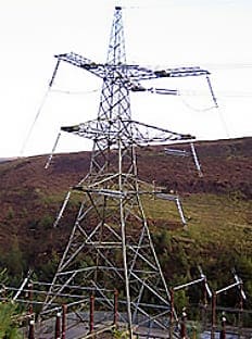
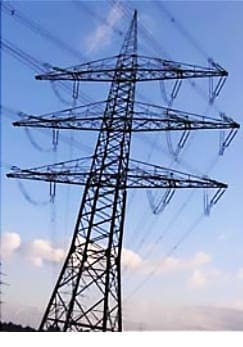
Three-level pylon
Three-level pylon is a pylon designed to arrange conductor cables on three crossbars in three levels. For two three-phase circuits (6 conductor cables), it is usual to use fir tree pylons and barrel pylons.
Three-level pylons are taller than other pylon types.
3. The Foundations
Gravity foundation
Gravity foundation of reinforced concrete slabs common foundation in normal ground. Difficulty to make cast large quantities of concrete.
Different temperature can be observed during the solidification causing thermal cracks and exposing the steel structure to corrosion.
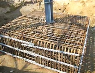
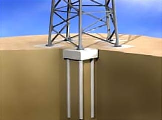
Pile foundation
Pile foundation with concrete slab used in difficult ground conditions (bored, tube driven into ground). Challenges related to the making of the piles with possibility dislocation.
Limited control possibilities towards the quality of the pile.
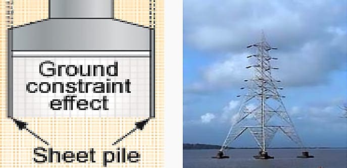
Sheet pile foundation
Sheet pile foundation with concrete slab used in difficult ground conditions (sheet piles driven / vibrated into ground).
Tendency to replace pile foundation as cheaper process without long running experience.
Transmission Line – Foundation (VIDEO)
Foundations of any structure plays on important role in safety and satisfactory performance of the structure as it transmits the loads from structure to earth.
The towers legs are usually set in concrete which generally provides good protection to the steel. Without having a sound and safe foundation, structure cannot perform the functions for which it has been designed.
Therefore, the importance of foundation needs not to be over emphasized.
4. Insulators, Bushings and Arresters
Insulators must support the conductors and withstand both the normal operating voltage and surges due to switching and lightning.
Insulators are broadly classified as either:
- Pin-type – which support the conductor above the structure, or
- Suspension type – where the conductor hangs below the structure.
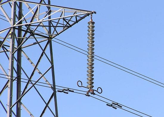
Suspension insulators are made of multiple units, with the number of unit insulator disks increasing at higher voltages. The number of disks is chosen based on line voltage, lightning withstand requirement, altitude, and environmental factors such as fog, pollution, or salt spray.
Longer insulators, with longer creepage distance for leakage current, are required in these cases. Strain insulators must be strong enough mechanically to support the full weight of the span of conductor, as well as loads due to ice accumulation, and wind.
The semiconducting glaze also insures a more even distribution of voltage along the length of the chain of insulator units.
Insulators for very high voltages, exceeding 200 kV, may have grading rings installed at their terminals. This improves the electric field distribution around the insulator and makes it more resistant to flash-over during voltage surges.
Here below the details on the equipment:
Insulators, Bushings and Surge arresters types
Basic Insulators
Basic insulators used to separate electrical conductors. Insulators are required at the points at which they are supported by utility poles or pylons.
Surge arresters are used to avoid damage to the electrical equipment through controlled conduction of the excess voltage (ex. lightning) either through flashover (preferred) or through the arrester itself by grounding.
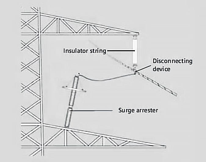
All of them are exposed to height mechanical stress after excess voltage damaging the mechanical structure of the arrester. Therefore particular attention is paid to avoid rupture after such event. The centre rod is the core part and continuously further developed.
Different designs are known.
Tube design (core – Fibre reinforced plastic tube)
Cage design (core – Fibre reinforced plastic rods)
Wrap design (code – Metal oxide varistor)
Bushings are specific insulators that required where the wire enters buildings or electrical devices, such as transformers or circuit breakers, to insulate the wire from the case. They are hollow insulators with a conductor inside them.
Materials , design: – Glass, porcelain, or composite polymer materials. Cap and pin design is to keep parts of the insulator dry to increase the insulation capacity in wet conditions and avoid flashover.
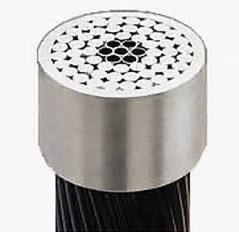
5. Conductors
Aluminium conductors reinforced with steel (known as ACSR) are primarily used for medium and high voltage lines and may also be used for overhead services to individual customers.
While larger conductors may lose less energy due to lower electrical resistance, they are more costly than smaller conductors. An optimization rule called Kelvin’s Law states that the optimum size of conductor for a line is found when the cost of the energy wasted in the conductor is equal to the annual interest paid on that portion of the line construction cost due to the size of the conductors.
The optimization problem is made more complex due to additional factors such as varying annual load, varying cost of installation, and by the fact that only definite discrete sizes of cable are commonly made.
Since a conductor is a flexible object with uniform weight per unit length, the geometric shape of a conductor strung on towers approximates that of a catenaries. The sag of the conductor (vertical distance between the highest and lowest point of the curve) varies depending on the temperature.
A minimum overhead clearance must be maintained for safety. Since the temperature of the conductor increases with increasing heat produced by the current through it, it is sometimes possible to increase the power handling capacity (up-rate) by changing the conductors for a type with a lower coefficient of thermal expansion or a higher allowable operating temperature.
Bundled conductors are used for voltages over 200 kV to avoid corona losses and audible noise.
Bundle conductors consist of several conductor cables connected by non-conducting spacers. For 220 kV lines, two-conductor bundles are usually used, for 380 kV lines usually three or even four. American Electric Power° is building 765 kV lines using six conductors per phase in a bundle. Spacers must resist the forces due to wind, and magnetic forces during a short-circuit.
Very high-voltage transmission lines may have two ground conductors. These are either at the outermost ends of the highest cross beam, at two V-shaped mast points, or at a separate cross arm.
Older lines may use surge arrestors every few spans in place of a shield wire, this configuration is typically found in the more rural areas of the United States.
By protecting the line from lightning, the design of apparatus in substations is simplified due to lower stress on insulation. Shield wires on transmission lines may include optical fibres (OPGW), used for communication and control of the power system.
Medium-voltage distribution lines may have the grounded conductor strung below the phase conductors to provide some measure of protection against tall vehicles or equipment touching the energized line, as well as to provide a neutral line in Wye wired systems.
While overhead lines are usually bare conductors, rarely overhead insulated cables are used, usually for short distances (less than a kilometre). Insulated cables can be directly fastened to structures without insulating supports.
An overhead line with bare conductors insulated by air is typically less costly than a cable with insulated conductors. A more common approach is “covered” line wire. It is treated as bare cable, but often is safer for wildlife, as the insulation on the cables increases the likelihood of a large wing-span raptor to survive a brush with the lines, and reduces the overall danger of the lines slightly.
These types of lines are often seen in the eastern United States and in heavily wooded areas, where tree-line contact is likely.
The only piffall is cost, as insulated wire is often costlier than its bare counterpart.
Many utility companies implement covered line wire as jumper material where the wires are often closer to each other on the pole, such as an underground riser/Pothead, and on re-closers, cut-outs and the like.
Conductor types
Suspended wires
Suspended wires for electric power transmission are bare, except when connecting to houses, and are insulated by the surrounding air.
Cooper has been replaced by Aluminium with steel wire core to provide the material strength.
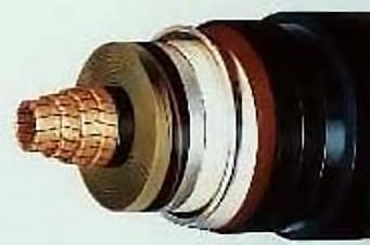
Underground cable – insulated
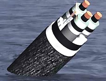
Sea cable – insulated
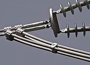
Surge arresters connection detail
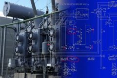
6. Substations
A transmission substation decreases the voltage of incoming electricity, allowing it to connect from long distance high voltage transmission, to local lower voltage distribution. It also reroutes power to other transmission lines that serve local markets.
A transmission substation may include phase-shifting or voltage regulating transformers.
This distribution is accomplished with a combination of sub-transmission (33 kV to 115 kV, varying by country and customer requirements) and distribution (3.3 to 25 kV).
Finally, at the point of use, the energy is transformed to low voltage (100 to 600 V, varying by country and customer requirements).
More, much more about substations you van find in our section ‘Power substations‘ as well as in article category ‘Substations‘
Sources: Construction of T&D lines by Ivan Blanco, XL Madrid Eric Brault, AXA Corporate Solutions (Chairman) Matia Cazzaniga, Zurich Roland Gmuer, AXA Corporate Solutions Martin Jenne, Munich Re Peter K6nigsberger, UNIQA Alberto Mengotti Foms, Mapfre Erik Poeplow, AXA Corporate Solutions Maurizio Colautti, Generali John Forder, Willis London Niels Kragelund, Codan David Walters, ACE


Your posts are very helpful
A phase of information to start with a very good one for consultations there is no time to learn new things
Thanks a lot
How to sizing of pylon and what are the sag , guy and anchor
VERY GOOD & INFORMATIVE
Interesantísimo este artículo, tanto como conocimiento o también para clases didácticas
Muy buen trabajo
Excellent information. Wish it was available before I retired as Professor!
You are simply the best; your presentations are superb. Thanks Edvard Csanyi.