
Estimated Study Time: 30 minutes
BCU and Digital Boolean Logic
The schematic drawings for the 132kV Line-1 Protection Panel (Bay-B102) provide a detailed, component-level view of how digital boolean logic is employed to govern the operation of high-voltage circuit breakers, isolators (disconnect switches), and earth switches.
 Technical Analysis of BCU Logic in 132kV Line Protection Panel Schematics (Bay-B102)
Operating within the framework of modern substation automation protocols (such as IEC 61850), the BCU enforces strict interlocking rules to prevent catastrophic switching errors, protect personnel, and ensure grid stability.
The transition from conventional hardwired relay logic to microprocessor-based Bay Control Units (BCUs) represents a critical evolution in high-voltage substation automation.
Grid coordinates (Page, Row, Column) are provided for precise traceability.
Here is the download link for the complete PDF document with drawings (85 pages). Open it up, so you can follow the discussion.
Schematics (PDF, 2.5 MB)
Table of Contents:
- A word about the Bay Control Unit (BCU)
- Bus 1 Isolator (B102-DSA) Interlock Logic:
- Bus 2 Isolator (B102-DS) Interlock Logic:
- Line Isolator and Earth Switch Logic:
- Bus Voltage Selection for Synchronizing Circuit
- Circuit Breaker (B102-CB) Trip and Close Logic:
- Conclusion
- ATTACHMENT (PDF) 🔗 Download ‘Substation Design Manual (445 pages)’
1. A word about the Bay Control Unit (BCU)
A Bay Control Unit (BCU) is a microprocessor-based intelligent electronic device used to monitor and govern the operation of a specific section, or “bay,” within a high-voltage substation. In the context of the 132kV Line-1 Protection Panel, the BCU serves as the central digital brain that physically executes all switching commands for the bay’s circuit breaker, bus isolators, and earth switches.
Its primary function is to enforce strict safety interlocking logic, mathematically guaranteeing that dangerous actions—such as opening an isolator under load or closing an earth switch on a live line—are physically blocked.
Ultimately, the BCU replaces vulnerable hardwired relays with a robust, programmable digital architecture that removes human error and protects both grid infrastructure and maintenance personnel.
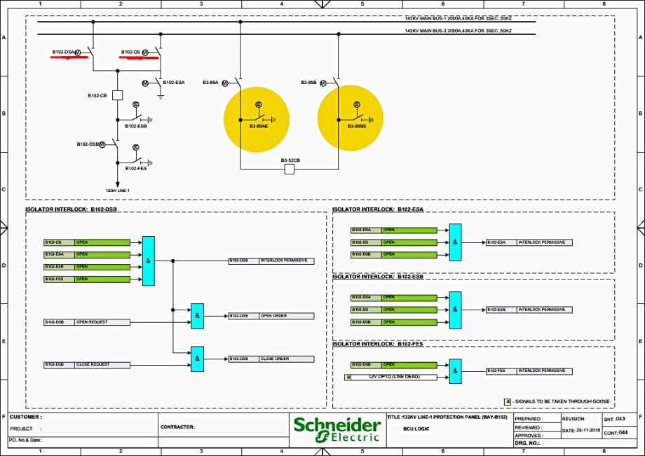
Figure 1 – 132kV Line Protection Bay-B102 (click to zoom)
2. Bus 1 Isolator (B102-DSA) Interlock Logic
(See Page 52)
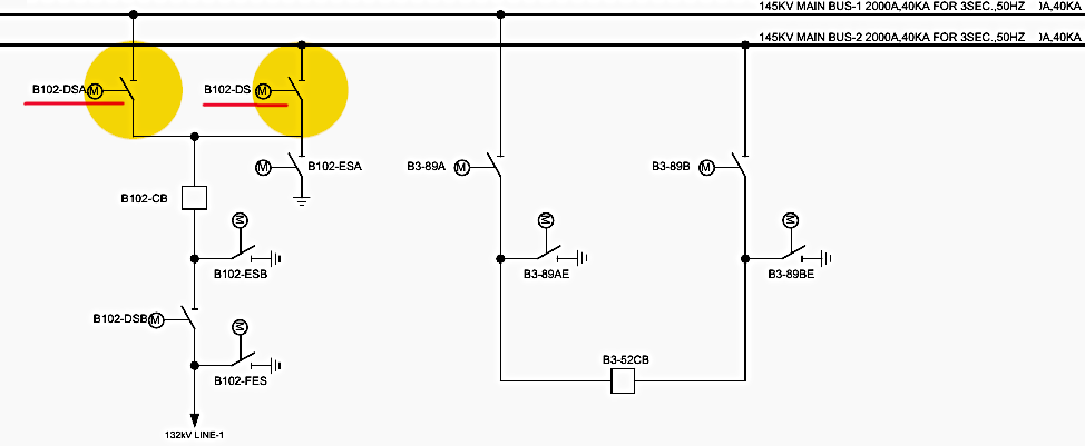
Page 52 (Schematic Sheet 041) is entirely dedicated to the interlocking permissive logic for the motorized Bus 1 Isolator, designated as B102-DSA. In a double main busbar system, such as the 145kV Main Bus 1 and Bus 2 layout utilized here, isolators are strictly off-load devices. They lack the specialized arc-quenching mediums (like SF6 gas or vacuum bottles) found in circuit breakers.
Consequently, opening or closing an isolator while load current is flowing will result in a deadly, unconfined electrical arc. The BCU logic prevents this by strictly controlling the “Interlock Permissive” signal.
The logic achieves this permissive state through two distinct operational paths: Normal Off-Load Switching and On-Load Bus Transfer.
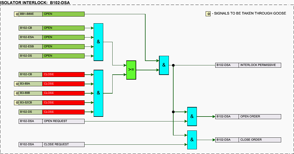
Figure 2 – Bus 1 Isolator (B102-DSA) Interlock Logic (click to zoom)
2.1 The Normal Off-Load Switching Path
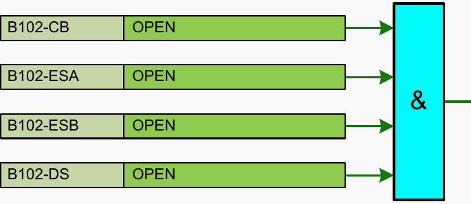
The first operational path represents the standard switching sequence where a bay is entirely de-energized before the isolator is moved. This logic is processed through a multi-input digital AND gate located at (Page 52, Row B, Column 4).
For this gate to output a true (1) signal, all of the following inputs must simultaneously register as true:
- B102-CB OPEN (Page 52, Row B, Column 2): This digital input confirms that the primary 132kV Circuit Breaker (B102-CB) is in the fully open state. This is the most critical check, ensuring that no load current is actively flowing through the bay.
- B102-ESA OPEN (Page 52, Row B, Column 2): This input verifies that the Bus-side Earth Switch is in the open position.
- B102-ESB OPEN (Page 52, Row B, Column 2): This verifies that the Line-side Earth Switch is open.Moving an isolator while an earth switch is closed could inadvertently connect a live busbar to ground.
- B102-DS OPEN (Page 52, Row B, Column 2): This verifies that the alternate bus isolator (Bus 2 Isolator, designated B102-DS) is open. This prevents the operator from tying Bus 1 and Bus 2 together through the bay without the proper synchronizing and bus coupler protocols.
Figure 3 – The Normal Off-Load Switching Path for Bus 1 Isolator (B102-DSA)
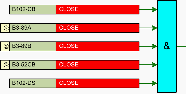
2.2 The On-Load Bus Transfer Path
Substation operators frequently need to transfer a live line from Bus 2 to Bus 1 without interrupting power to the consumer. This requires a precise “make-before-break” operation, which is governed by the second AND gate located at (Page 52, Row C, Column 4).
To safely close B102-DSA while the bay is actively carrying load from Bus 2, the two busbars must be at the exact same electrical potential. This path requires:
- B102-CB CLOSE (Page 52, Row C, Column 2): The bay’s circuit breaker must be closed, actively carrying the load.
- B3-89A CLOSE (Page 52, Row C, Column 2): This confirms that the Bus 1 Isolator for Bay 3 (the Bus Coupler Bay) is closed.
- B3-89B CLOSE (Page 52, Row C, Column 2): This confirms that the Bus 2 Isolator for the Bus Coupler Bay is closed.
- B3-52CB CLOSE (Page 52, Row C, Column 2): This confirms that the Bus Coupler Circuit Breaker is closed.The combination of B3-89A, B3-89B, and B3-52CB guarantees that Bus 1 and Bus 2 are rigidly tied together and share identical voltage and phase angles.
- B102-DS CLOSE (Page 52, Row C, Column 2): This confirms that the bay is currently fed from Bus 2.
Note that signals marked with @ are signals to be taken through GOOSE.
Figure 4 – The On-Load Bus Transfer Path for Bus 1 Isolator (B102-DSA)
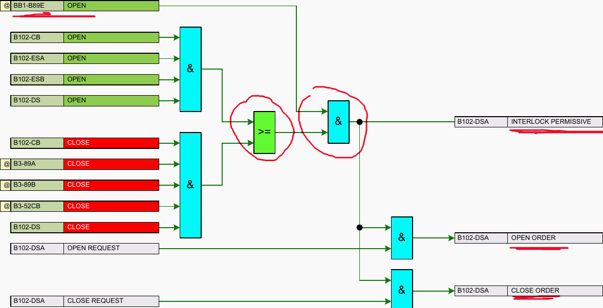
2.3 Final Safety Evaluation and Order Execution
The outputs from the Normal Switching AND gate and the Bus Transfer AND gate are fed into a logical OR gate (>=) located at (Page 52, Row C, Column 5). If either the safe de-energized condition OR the safe bus-tie condition is met, the signal passes forward.
However, before the final permissive is granted, the signal enters one last AND gate at (Page 52, Row B, Column 6), which checks a supreme safety override:
- BB1-889E OPEN (Page 52, Row A, Column 1): This input confirms that the Busbar 1 Main Earth Switch is open. If Busbar 1 is grounded for maintenance, closing B102-DSA would create a direct phase-to-ground fault. This input acts as an absolute block.
Once the B102-DSA INTERLOCK PERMISSIVE is generated, it routes to two downstream AND gates (Page 52, Rows D and E, Column 6).
- If the operator issues a B102-DSA OPEN REQUEST (Page 52, Row D, Column 2), it is ANDed with the permissive to generate the B102-DSA OPEN ORDER (Page 52, Row D, Column 8) sent to the motor contactor.
- Similarly, a B102-DSA CLOSE REQUEST (Page 52, Row E, Column 2) is ANDed with the permissive to generate the B102-DSA CLOSE ORDER (Page 52, Row E, Column 8).
Figure 5 – Final Safety Evaluation and Order Execution for Bus 1 Isolator (B102-DSA)
3. Bus 2 Isolator (B102-DS) Interlock Logic
(See Page 53)
Page 53 (Schematic Sheet 042) mirrors the rigorous logic detailed on the previous page, but it is entirely dedicated to the Bus 2 Isolator, designated as B102-DS (frequently referred to as DSB in corresponding SLD conventions, though labeled B102-DS in this logic block).
The philosophical requirement remains identical: prevent the mechanical operation of the isolator unless the bay is safely isolated or a continuous, synchronized bus parallel exists via the bus coupler.
Note that signals marked with @ are signals to be taken through GOOSE.
Related electrical guides & articles


Edvard Csanyi
Hi, I'm an electrical engineer, programmer and founder of EEP - Electrical Engineering Portal. I worked twelve years at Schneider Electric in the position of technical support for low- and medium-voltage projects and the design of busbar trunking systems.I'm highly specialized in the design of LV/MV switchgear and low-voltage, high-power busbar trunking (<6300A) in substations, commercial buildings and industry facilities. I'm also a professional in AutoCAD programming.
Profile: Edvard Csanyi
