
Estimated Study Time: 40 minutes
Introduction and System Architecture
The DELA ROSA 230kV Substation represents a critical node in high-voltage power transmission, utilizing a highly integrated outdoor Gas Insulated Switchgear (GIS) topology. The reference engineering documentation specifies a comprehensive 245kV implementation, structured predominantly around Siemens Energy’s 8DN9 and 8DQ1 switchgear platforms. For your reference, the complete 713-page PDF of the switchgear documentation and drawings is included.
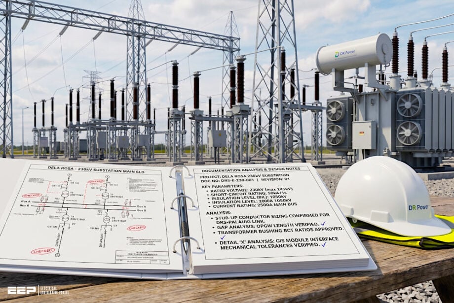 Technical Analysis of Engineering and Design Documentation for the DELA ROSA 230kV Substation
The deployment is engineered to accommodate a rated maximum continuous voltage of 245kV at a nominal frequency of 60Hz, with permissible frequency variations between 57.5Hz and 62.5Hz.
The architecture is fundamentally aligned with digital substation paradigms, incorporating an IEC 61850-based Power Management System (PMS) to facilitate advanced Substation Configuration Language (SCL) methodologies and robust IT/OT convergence.
The GIS equipment utilizes sulfur hexafluoride (SF6) as the primary dielectric medium, employing a three-phase encapsulated main busbar configuration, while ancillary equipment such as circuit breakers and disconnect switches employ single-phase encapsulation.
Ready for a deep dive? Grab a coffee, settle in, and let’s get started.
- Primary Equipment Specifications:
- Protection, Control, and Telecommunication Architecture:
- Civil and Structural Engineering Analysis:
- High-Voltage Clearances and Spatial Arrangements
- Grounding and Lightning Protection Implementation:
- Local Control Cubicles (LCC) and Wiring Schematics
- Cable Termination Enclosures and Assembly Protocols
- Transformer Online Gas Monitoring System
- GIS Packing and Delivery Logistics
- Comprehensive Analysis of 230kV GIS Substation Feeder/Coupler:
- Conclusion
- ATTACHMENT (PDF) 🔗 Download 230kV Substation Documentation and Drawings (713 pages, 87,5 Mb)
1. Primary Equipment Specifications
The primary high-voltage apparatus is subject to rigorous electromechanical and dielectric parameters. The overall insulation level is defined by a Basic Impulse Level (BIL) of 1050kV peak for phase-to-earth gaps and 1200kV peak across open isolating distances.
The rated short-duration power frequency withstand voltage is established at 460kV rms for phase-to-earth constraints and 530kV across open gaps. The short-time withstand current for the primary circuit is 50kA rms for a duration of 3 seconds, coupled with a dynamic peak withstand current of 130kA.
1.1 Circuit Breakers
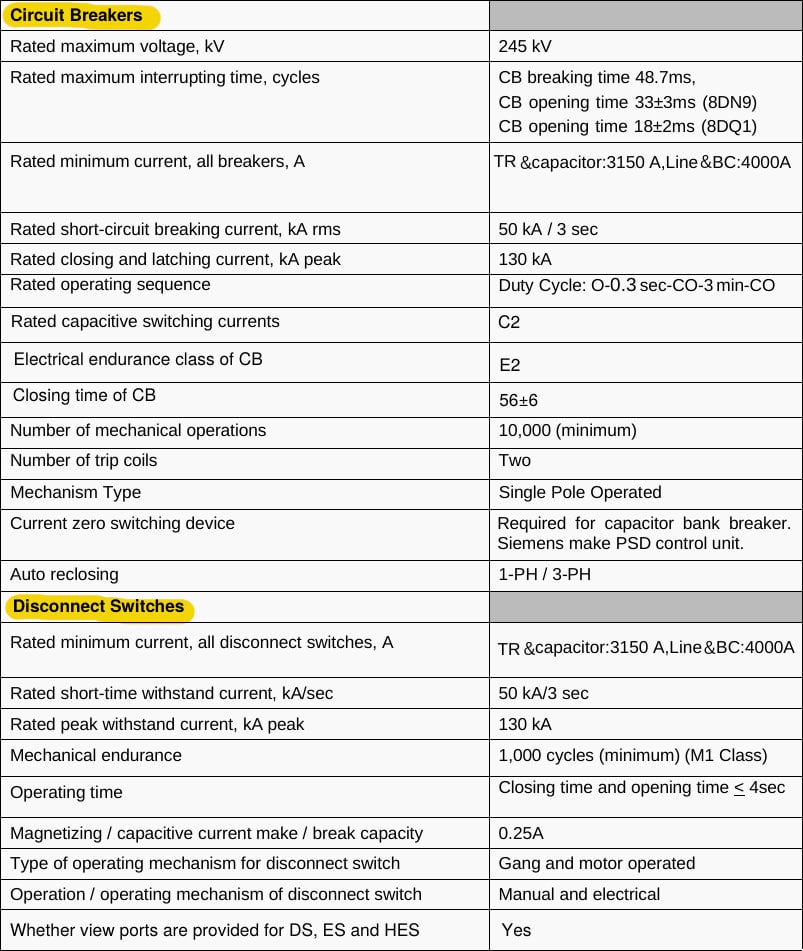
The installation employs specific circuit breaker variants depending on the functional bay. Breakers assigned to the transformer and capacitor bank feeders possess a rated minimum continuous current of 3150A.
In contrast, the line and bus coupler circuit breakers are rated for 4000A.
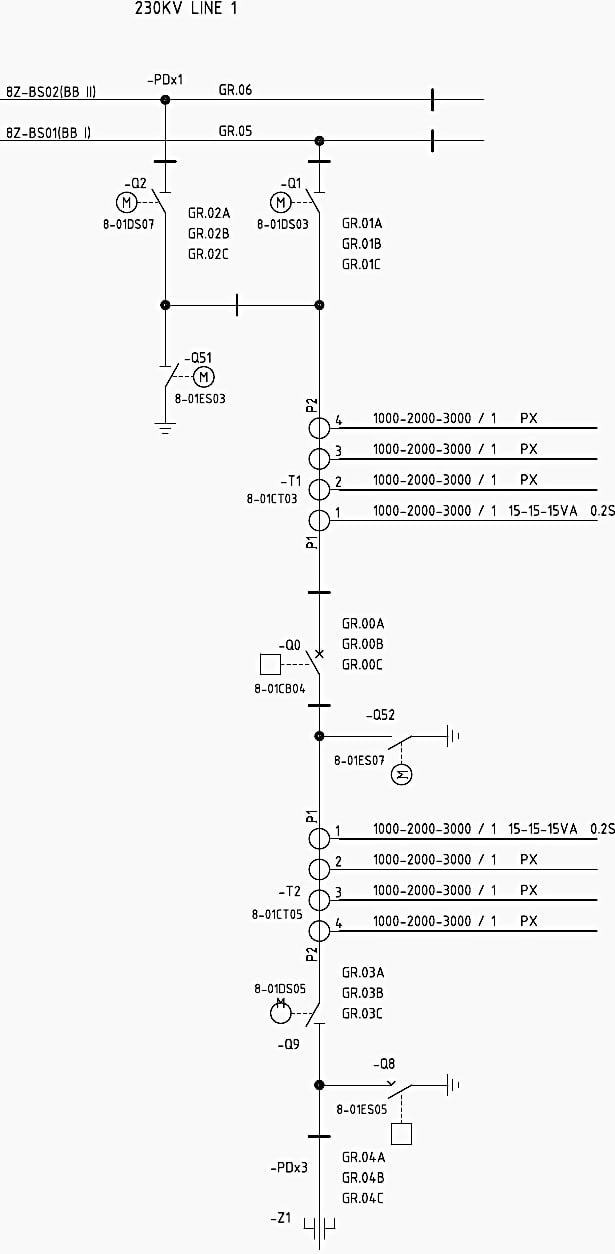
The 8DN9 breaker variants exhibit a breaking time of 48.7ms and an opening time of 33±3ms, whereas the 8DQ1 variant achieves an opening time of 18 ±2ms. The capacitor bank breakers are augmented with a Phase Synchronizing Device (PSD) to manage current zero switching and mitigate capacitive switching transients.
See pages 25 and 26.
Figure 1 – 8DN9 GIS swichgear feeder
1.2 Disconnect and Earthing Switches
The disconnect switches (DS) are motor-operated, facilitating both manual and electrical gang operation. They are rated for a mechanical endurance of 1,000 cycles (Class M1) and are capable of interrupting the charging current of the connected GIS bus.
The magnetizing and capacitive current make/break capacity is 0.25A. Standard earthing switches (ES) and high-speed grounding switches (HSGS) are rated for a minimum continuous current of 1250A and a short-time withstand of 50kA for 3 seconds.
The spring charging time for the HSGS is 6 seconds, achieving closing and opening times of less than 60ms, compared to the standard grounding switch operation time of less than 4 seconds.
See pages 26 and 27.
Figure 2 – CBs, Disconnect and Earthing Switches Datasheets
1.3 Instrument Transformers and Bushings
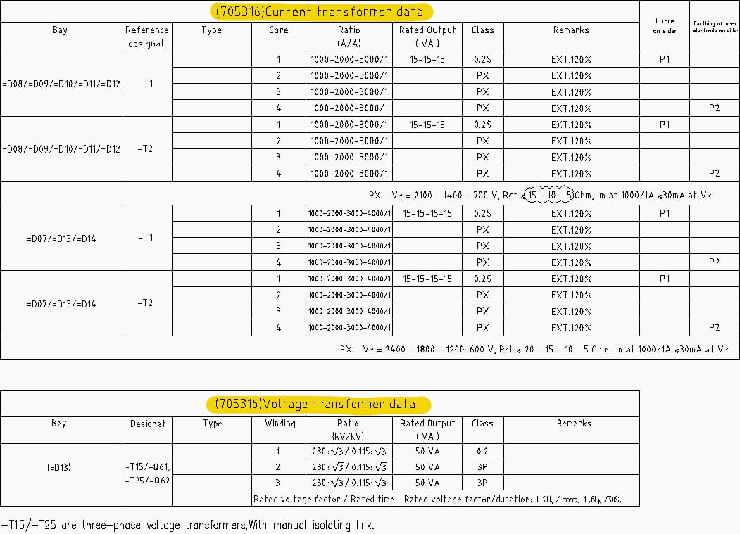
Voltage Transformers (VT) are SF6 gas-insulated, electromagnetic types designed for three-phase, phase-to-ground applications within an effectively grounded system. The VTs incorporate a disconnecting link to permit isolation during high-voltage AC testing, and exhibit a partial discharge value of ≤ 5 pC at 1.2Ur / √3.
The VTs step down the 230kV primary voltage to 115V or 115/√3V secondary potentials. The metering windings provide a 50VA output at an accuracy class of 0.2, while the protection windings deliver 50VA at a 3P accuracy class.
The VTs are rated for a continuous voltage factor of 1.2 and a short-duration factor of 1.5 for 30 seconds.
Current Transformers (CT) feature variable ratios to accommodate differing protection and metering requirements. The 230kV CTs are specified with ratios ranging from 1000-2000-3000/1 A up to 1000-2000-3000-4000/1 A.
For example, the 4000/1 A ratio PX core exhibits a knee point voltage of 2400V and an internal resistance of 20 Ohms.
See page 34.
Figure 3 – Instrument transformers datasheet
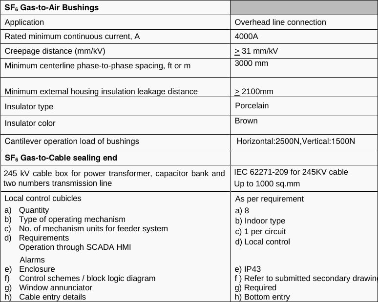
The SF6 gas-to-air bushings, utilized for overhead line interfaces, consist of brown porcelain insulators with a minimum centerline phase-to-phase spacing of 3000mm. These bushings support a 4000A continuous current and provide a creepage distance exceeding 31 mm/kV, resulting in an external housing insulation leakage distance greater than 2100mm.
The cantilever operational load is rated at 2500N horizontally and 1500N vertically.
Additionally, 245kV cable sealing ends comply with IEC 62271-209, accommodating cross-sections up to 1000 sq.mm for the power transformer, capacitor bank, and transmission lines.
See page 28.
Figure 4 – SF6-gas-to-air bushings datasheet
1.4 SF6 Gas Parameters and Busbar Characteristics
The SF6 insulation system maintains strict pressure regulation across independent compartments. The nominal filling pressure for the 8DN9 circuit breakers is 6.9 bar, with a defined SF6 density minimum of 6.2 and 6.4 bar. The 8DQ1 (3150A) breaker operates at a lower filling pressure of 5.6 bar.
Other GIS compartments are maintained at 6.1 bar.
The GIS busbar consists of a solid aluminum conductor with an outer diameter of 80mm. The busbar electrical parameters include an inductance of 0.2 ± 0.04 μH/m, a resistance of 8 μΩ/m, a surge impedance of 60 ±12Ω, and a capacitance of 50 ±10 pF/m. The outer enclosure for the busbar has a diameter of 561mm and a wall thickness of 13mm.
Good Reading – SF6 Gas Monitoring and Alarming Practices in GIS Substations
SF6 Gas Monitoring and Alarming Practices in Gas-Insulated Switchgear (GIS) Systems
2. Protection, Control, and Telecommunication Architecture
The secondary protection schemes and control networks form the deterministic infrastructure of the DELA ROSA substation. The Network Data Management Equipment (NDME) processes analog and digital signals from Intelligent Electronic Devices (IEDs) across the installation.
2.1 NDME Signal Input Configuration
(NDME – Network Data Management Equipment)
The signal input list delineates the specific analog and digital channels required for various protection zones.
For Busbar Protection, the NDME monitors three analog channels: LV Phase A, LV Phase B, and LV Phase C. The digital channels assigned to busbar protection include Bus Differential Trip (87B), Relay Fail, DC Fail, AC Fail, and Voltage Low. Breaker failure protection (integrated within the double busbar scheme) relies on digital inputs for:
- Breaker Fail Start,
- Breaker Fail Trip,
- Breaker Fail Retrip,
- Autorecloser Successful,
- Autorecloser Not Ready,
- Definitive Trip,
- Relay Fail,
- DC Fail, and
- AC Fail.
The Shunt Capacitor Protection system utilizes an extensive array of analog channels to monitor unbalance and phase deviations. These include Phase A, B, and C voltages and currents, and the neutral current. The corresponding digital channels trigger on:
- Overcurrent Start,
- Overcurrent Trip,
- Star Unbalance Trip,
- Overvoltage Alarm,
- Overvoltage Trip,
- VT Fail,
- Relay Fail,
- DC Fail, and
- AC Fail.
Suggested Study – Restricted earth fault relay application within a 400kV shunt capacitor bank design
Restricted earth fault relay application within a 400kV shunt capacitor bank design
Transformer Protection involves eighteen analog channels to capture the complete primary and secondary current and voltage phasors. Secondary side inputs mirror the primary configuration, while high-voltage and medium-voltage bushing current transformers (BCTs) provide additional analog current inputs. The digital protection channels for the transformer execute
- General Start,
- Differential Trip (87T),
- Restricted Earth Fault (REF) Trip (64T),
- Primary Overcurrent Trip,
- Secondary Overcurrent Trip,
- Overfluxing Protection Trip,
- Distance Trip,
- Ground Protection Trip,
- Tertiary Winding Protection Trip,
- Relay Fail,
- VT Fail,
- DC Fail,
- AC Fail,
- Buchholz Main Tank,
- Buchholz OLTC,
- Pressure Relief,
- Winding Temperature, and
- Oil Temperature.
Line Differential Protection evaluates Phase A, B, and C voltages, alongside the currents from the main breaker (Phases A, B, C, Neutral) and the tie breaker (Phases A, B, C, Neutral). Digital channels facilitate General Start, Differential Trip, Trip via DTT, Communication Failure, Distance Zone 1/2/3 Trips, Switch-Onto-Fault, Power Swing Block, DTT Receive, Autoreclose Initiate, Autoreclose Block, Stub Protection Enable, and Distance Protection Block.
All interface connections between the NDME and individual protection relays are hardwired to ensure deterministic signal latency.
Figure 5 – NDME Signal Input listed in line differential relay

2.2 Substation Automation System and Telecommunications
The Power Management System (PMS) defines the overarching IEC 61850 network topology. The architecture incorporates redundant NDME panels and protection relays networked via industrial Ethernet switches. A GPS panel supplies the IRIG-B timing signal necessary for precise event stamping and synchrophasor measurement alignment across the PMS Master Station and the PMS Slave.
The telecommunication layer integrates a Traveling Wave Fault Locator (TWFL) network connecting the DELA ROSA substation with the BOTOLAN and NGCP PALAUIG substations. The TWFL panels at each site derive precise timing from local GPS receivers and interface via optical ground wire (OPGW) transmission lines.
The OPGW splice boxes facilitate the transition of the optical fibers into the substation control room.
Related electrical guides & articles


Edvard Csanyi
Hi, I'm an electrical engineer, programmer and founder of EEP - Electrical Engineering Portal. I worked twelve years at Schneider Electric in the position of technical support for low- and medium-voltage projects and the design of busbar trunking systems.I'm highly specialized in the design of LV/MV switchgear and low-voltage, high-power busbar trunking (<6300A) in substations, commercial buildings and industry facilities. I'm also a professional in AutoCAD programming.
Profile: Edvard Csanyi
