
Estimated Study Time: 26 minutes
The Symphony of Impending Failure
Let ‘s talk about the acoustic diagnostics of low-voltage substations, focusing on the ten most dangerous acoustic emissions, their underlying physics, and diagnostic methodologies. In the realm of electrical distribution, low-voltage (LV) substations—typically operating at or below 1000V AC—form the critical nexus between medium-voltage distribution networks and end-user loads.
 The Ten Most Dangerous Noises in a Low-Voltage Substation
While sophisticated supervisory control and data acquisition (SCADA) systems monitor voltage, current, and thermal telemetry, one of the most vital diagnostic metrics remains acoustic emission.
A substation is never truly silent; it operates with a baseline acoustic signature dictated by electromagnetic forces and fluid dynamics. However, deviations from this baseline—specifically anomalous sounds—serve as early-warning indicators of mechanical fatigue, dielectric breakdown, and impending catastrophic failure.
Before analyzing specific noises, it is crucial to understand how sound is generated in an inherently non-mechanical system like an electrical substation. Acoustic emissions in electrical equipment are primarily driven by three mechanisms:
The first one belongs to Electromagnetic Forces. Alternating current generates alternating magnetic fields. These fields interact with ferromagnetic materials (causing magnetostriction) and current-carrying conductors (generating Lorentz forces), converting electrical energy into mechanical vibration.
Second mechanism is actually the Dielectric Breakdown. When electrical stress exceeds the dielectric strength of an insulator (air, epoxy, or polymer), ionization occurs. The rapid expansion of localized plasma creates acoustic shockwaves, ranging from ultrasonic hissing to explosive detonations.
The third mechanism is a Mechanical/Thermal Degradation. Friction in moving parts (cooling fans, breaker mechanisms) or the thermal expansion/contraction of materials subjected to heavy Joule heating (P = I2R) produces mechanical noise.
When maintenance personnel or acoustic sensors detect the following ten sounds, immediate investigative action is required.
Here is a comprehensive technical article detailing the acoustic diagnostics of low-voltage substations, focusing on the ten most dangerous acoustic emissions, their underlying physics, and diagnostic methodologies.
- The Explosive “Bang”: Arc Flash and Dead Short Circuits
- Continuous High-Frequency Hissing: Surface Tracking and Insulation Degradation
- Amplified, Non-Sinusoidal Humming: Harmonic Distortion and Core Saturation
- Rapid Chattering or Buzzing: Contactor and Relay Coil Failure
- Sizzling or “Frying”: Loose Connections and Series Arcing
- Rhythmic Thumping or Clanging: Electrodynamic Forces on Busbars
- Sharp, Sporadic Snapping or Popping: Dielectric Breakdown in Cast Resin
- High-Pitched Squealing: Cooling Fan Bearing Degradation
- Low-Frequency Rattling: Mechanical Resonance and Fastener Fatigue
- Muffled Rumbling or Boiling: Insulating Fluid Degradation
- Modern Acoustic Monitoring Systems: Moving from Reactive to Condition-Based Maintenance
- Conclusion
- BONUS (PDF) 🔗 Download ‘Theoretical and Practical Guide to Power System Protection’
1. The Explosive “Bang”: Arc Flash and Dead Short Circuits
The Sound: A deafening, instantaneous detonation, often accompanied by a blinding flash of light and a concussive shockwave.
The Physics: This sound is the result of an arc flash—a rapid release of energy caused by an arcing fault between phase busbars, neutral, or ground. When the dielectric medium (usually air in LV switchgear) breaks down, a plasma channel forms. The temperature of this arc can exceed 20,000°C (significantly hotter than the surface of the sun).
This intense heat causes the surrounding air and vaporized copper/aluminum to expand at supersonic speeds. The equation for the energy released during this event is proportional to the arc voltage, fault current, and duration:
The Danger: The acoustic shockwave (often exceeding 140 dB) can rupture eardrums, but it is merely a byproduct of the lethal thermal radiation and shrapnel.
Diagnostics and Mitigation: By the time this sound is heard, the failure has occurred. Mitigation relies on preventative technologies such as arc-flash relays equipped with optical sensors that detect the light of an incipient arc and trip the upstream breaker in under 2 milliseconds, significantly reducing the incident energy.
Watch Video – A seemingly harmless situation ended with an arc flash and a bang
2. Continuous High-Frequency Hissing: Surface Tracking and Insulation Degradation
The Sound: A continuous, high-pitched hiss, similar to a leaking pressurized gas pipe or frying bacon.
The Physics: While true corona discharge is rare in LV environments (typically requiring voltages above 5kV), a similar acoustic profile is generated by surface tracking. This occurs when dust, moisture, or chemical contaminants settle on the surface of insulators (like busbar supports or standoff insulators).
The Danger: Surface tracking is progressive. The carbon tracks permanently degrade the creepage distance of the insulator. Left unchecked, the tracks will bridge the gap between phase and ground, culminating in a phase-to-ground fault and a subsequent arc flash.
Diagnostics and Mitigation: Because much of this acoustic energy is in the ultrasonic range (above 20 kHz), ultrasonic acoustic detectors are required to pinpoint the source. Mitigation involves regular cleaning of insulators, improving substation environmental controls (HVAC/dehumidification), and utilizing conformal coatings on vulnerable components.
Watch Video – Ultrasonic detection of damage in insulation
3. Amplified, Non-Sinusoidal Humming: Harmonic Distortion and Core Saturation
The Sound: A loud, harsh, and fluctuating hum emanating from dry-type transformers, distinctly different from the smooth, steady baseline hum of standard operation.
The Physics: The baseline hum of a transformer is caused by magnetostriction—ferromagnetic core steel expanding and contracting as the magnetic domains align with the alternating magnetic flux. The fundamental frequency of this vibration is twice the line frequency (e.g., 100 Hz in a 50 Hz system, or 120 Hz in a 60 Hz system).
Furthermore, if the core is pushed into magnetic saturation due to overvoltage, the magnetostrictive forces spike non-linearly.
Watch Video – 1600 kVA medium voltage power transformer humming at 50 Hz grid frequency. Actual noise varies with power load and current higher harmonics
The Danger: Excessive harmonic vibration leads to mechanical fatigue of the core laminations, breakdown of the insulation between laminations (causing eddy current heating), and severe overheating of the transformer windings, drastically reducing the equipment’s lifespan.
Diagnostics and Mitigation: Acoustic spectrum analysis using a Fast Fourier Transform (FFT) algorithm can separate the acoustic frequencies. If high-amplitude peaks are found at 300Hz, 500Hz, etc., harmonic pollution is confirmed.
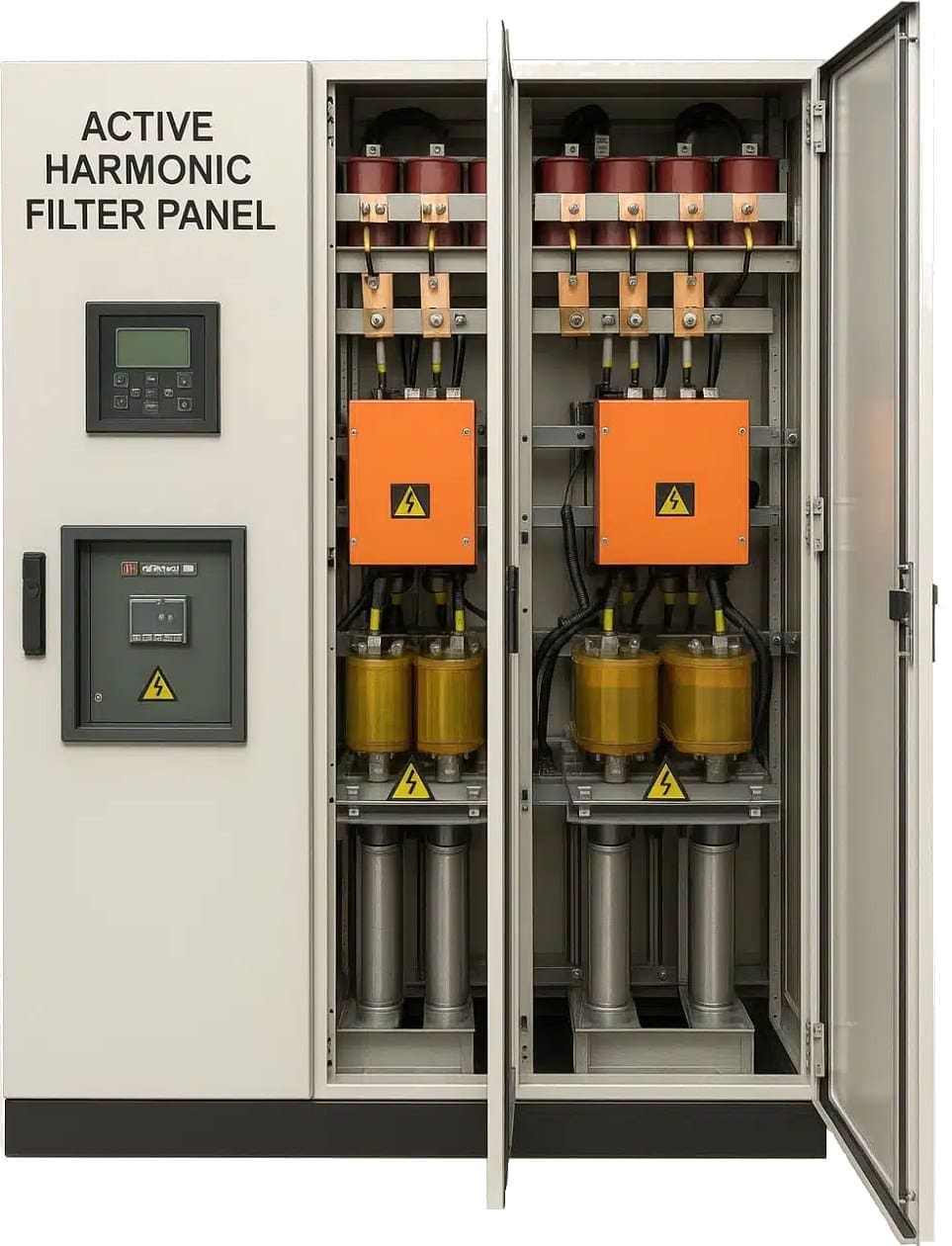
Mitigation requires installing active harmonic filters or utilizing K-rated transformers designed to withstand harmonic heating.
Figure 1 – Low-voltage active harmonic filters
4. Rapid Chattering or Buzzing: Contactor and Relay Coil Failure
The Sound: A harsh, rapid mechanical clicking or loud, localized buzzing coming from control panels, Motor Control Centers (MCCs), or automatic transfer switches (ATS).
The Physics: Electromechanical contactors use a magnetic coil to pull armatures together to close electrical contacts. Because alternating current passes through zero twice per cycle, the magnetic pull also drops to zero, which would cause the contacts to chatter. To prevent this, a “shading ring” (a shorted copper turn) is embedded in the pole face of the electromagnet.
This ring induces a delayed magnetic flux, maintaining an attractive force during the AC zero-crossing.
Related electrical guides & articles


Edvard Csanyi
Hi, I'm an electrical engineer, programmer and founder of EEP - Electrical Engineering Portal. I worked twelve years at Schneider Electric in the position of technical support for low- and medium-voltage projects and the design of busbar trunking systems.I'm highly specialized in the design of LV/MV switchgear and low-voltage, high-power busbar trunking (<6300A) in substations, commercial buildings and industry facilities. I'm also a professional in AutoCAD programming.
Profile: Edvard Csanyi
