
General description of site test procedure
Site test procedure covers all necessary electrical testing for the 110 kV cable and accessories to be carried out during and after installation of the cable system. This procedure is in line with the requirements of the contract suitable for 110 kV, XLPE cables and accessories and the tests are in accordance with TCSP-104.08, IEC 229, IEC 540 and IEC 840.
110 kV, 115 kV and 132 kV XLPE Cables
(Standard Reference is IEC 60840 and relevant SEC Transmission Specifications 11-TMSS-02, Rev. 0 and TCS-P-104.02, TCS-P-104.03, TCS-P-104.06 and TCS-P-104.08)
1. Mechanical Check and visual Inspection
| ITEM | Description | Remark |
| 1 | Inspection for physical damage or defects | |
| 2 | Check tightness of all bolted connections (torque wrench method) | |
| 3 | Check for proper cable bolted connections | |
| 4 | Check cable bends to ensure that bending radius is equal to or greater than the minimum bending radius specified | |
| 5 | Check for proper cable support, clamping, trays arrangements | |
| 6 | Link box tightness check | |
| 7 | Verify that shields are terminated as specified (through link box or directly grounded) | |
| 8 | Verify the exact route length as per approved drawings from terminations to terminations | |
| 9 | Check that all grounding points are securely connected to ground grid as specified | |
| 10 | Check that phases are identified and color coded | |
| 11 | Single core cable connected between power transformer and switchgear shall be single point earthed as switchgear side and at floating side SVL (sheath voltage limiter) should be installed | |
| 12 | Check single point or both ends, via voltage limiter as per approved design | |
| 13 | Inspection of label inside link boxes and water proofing | |
| 14 | Check cable entry path trench as ducts are properly sealed | |
| 15 | Check irregularities of outer jacket formed by non-uniform shield wire distribution | |
| 16 | Check/inspect the transposition of cable phases | |
| 17 | Check the cable outer jacket for any physical damage during and after installation | |
| 18 | Check for the cross connection of cable metallic sheath in cross bonding system | |
| 19 | Check the rubber seal in cable clamps to avoid any damage to cable outer jacket | |
| 20 | Check the insulating shrouds are installed at the base of the cable terminations | |
| 21 | For accessories (sealing terminations, instrument panels and link boxes) check the following: | |
| a. Name plates installed and data is correct | ||
| b. Danger signs | ||
| c. Bolt tightness check and paint work conditions |
2. Electrical Test
(Standards Reference is IEC 60840, and relevant SEC Transmission specifications 11-TMSS-02, TCS-P-104.08).
| ITEM | Description | Remark |
| 1 | Check Phasing for Conductor and sheath bonding | |
| 2 | Sheath DC high voltage test (10 kV DC for 1 min.) and 5 kV DC insulation test before and after high voltage/24 hour soaking test | |
| 3 | Conductor resistance, capacitance and inductance measurement test | |
| 4 | Conductor insulation resistance test | |
| 5 | Cross-bonding verification test | The sheath current should be <3% the current due to induction neighboring circuits should be considered and limit should be 3%+current due to external circuits |
| 6 | Zero and positive sequence impedance measurement | |
| 7 | SVL (Sheath/Surge voltage Limiter) test by 2.5 kV DC insulation tester | |
| 8 | Measure the ground resistance at all link box positions as per SEC standards TES-P-104.08) | |
| 9 | Contact resistance test on link boxes (less than 20 μΩ) | |
| 10 | Metallic sheath continuity test | |
| 11 | Cable profile test- during jointing | |
| 12 | In case of Double Circuit (110 kV and above), check the separate grounding pit | |
| 13 | AC High voltage test for all new cables, but if old portion are involved then soaking for 24 hours at rated voltage |
1. Phase indication test
After complete installation, the cables are to be identified with respect to their phases and are to be reconfirmed whether they are correctly marked or not.

Equipment / Instruments Used
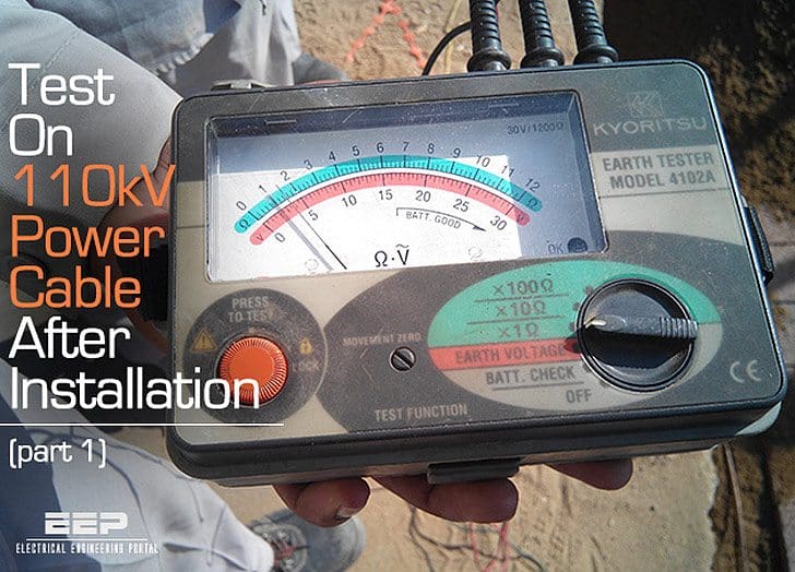
Battery operated KYORITSU, High Voltage Insulation Resistance Tester, and MODEL-3125

Instructions
- The screens of all cables at one end are to be shorted and grounded.
- The conductor of the cable under test is to be connected to the negative pole of the meter.
- The positive pole of the meter is to be grounded.
- Through a switch ground the other end of this conductor of the cable under test and measure the resistance.
- If the resistance becomes zero, the phase identification is ok and checks whether the correct color coding is applied or not.
- To cross check, open the switch, the meter shall read high resistance (Tending to infinity).
- Similarly repeat the test for other phases and verify the correctness of color coding.
2. DC Conductor Resistance Measurement
The DC resistance of conductors of the cables, to be measured at ambient temperature before conducting any other test, and the values are to be computed for 20ºC.

Reference
- IEC 60228 – Conductors of insulated cables
Equipment / Instruments used
- Any wheatson bridge, micro Ohm-Meter.
- Any industrial type thermometer to measure the ambient temperature.
Instructions
- The conductors are short circuited at the far end by minimum 95 mm2 cable.
- The other ends of the cable are connected to the bridge according to equipment instructions.
- Note down the measured value.
- The resistance of conductor at 20ºC/km is obtained by substituting the measured value in the formula.
For Copper R20 = R/L (1 + 0.00393*(T-20)) Ω/KM
Where,
- R20 – Conductor resistance at 20ºC *(ohm/km
- R – Measured resistance of one phase (ohm)
- L – Exact length (km)
- 0.00393 – Temperature coefficient at 20ºC for copper (K)
- T – Temperature of conductor when measured in ºC
3. Capacitance Test
The capacitance shall be measured between conductor and metallic screen. According to IEC, the measured value shall not sxceed the normal value specified by the manufacturer by more than 8%.

Reference
- IEC 60840 – Applies to cable voltage ratings between 30 kV and 150 kV. It includes a regular type test sequence for cables and a separate sequence for the cable accessories.
Equipment / Instruments used
Any RLC bridge capable of measuring capacitance up to 0.01 micro-farad (μF)

Instructions
- Connections are made as per below schematic.
- Connect the instrument cable between conductors and metallic screen and take the measurements.
- The capacitance is measured between each individual conductor and sheath. A capacitance bridge is used for this measurement.
- The value obtained can be converted to μF/km
C = Cm/L (μF/km)
Where:
- C – Capacitance in μF/k
- Cm – Measured Capacitance in μF
- L – Length of Cable in km.
To be continued soon…


Which mode should be selected for capacitance and dissipation factor test
pls is the standard also for overhead lines
Dear Eng. Zafar
I really thank you for providing us with these information of HV cables site tests and we have learnt from them well.
we are waiting to learn more from you in the field of electrical power transmission
thank you
Dear Eng.Zafar,
You are really doing a good job by providing necessary information regarding field testing of power cable.I would like to suggest, please mention the specific standard of each testing, clear connection drawing of testing and achievable values of testing.it would be even better if you please provide this information.
Anyhow, the overall article was so good and keep up the good work.
Best of luck for the rest of your life.
Dear Sirs,
what differ between shield and screen in medium voltage armored cable where I need to do test between continuity test between shield and screen.
Thank you,
Hadi
Nice work ! keep it up .. Why there is earth tester in the picture instead of HV insulation tester ? (3124 ….)
Why earthing one end only for single core cable
That is to avoid making the cable screen (Grounding) a part of the Grounding system of the Network (or Substation), if not then a huge earth fault will be induced in it and may damage the cable (because it is not made for this purpose).
Dear sir, we need a instrument which can identify the presence of under ground power lines as we are in the task of digging on road sides for construction without disturbing the utilities. Kindly give your suggestions
I am indeed grateful on how this EEP have educated me on electrical repairs,maintenance and installation. Thanks.
I dearly need a hard copies of this EEP as concerns all treated topics.
Warm regards,
Emamomo Justin ( Nigerian)
zafar saab good article for testing
Zafer sahab good article, BUT not good to copy and paste SEC standard
thank you jalees sahab, please go through the whole article. its not copy-paste. i take the references of SEC standards and i mentioned this in it.
Thanks for the article, I used it as a guide to develop my write up about cable testing. But notheless, I would require you to give me some standards for cable testing in a tabular format, equipment used and the expectations (result).
Thanks
How test instsllrd ACSR CONDUCTOR?
I am working in Power house in operation + maintenance it is very interesting and informative .You are doing good for others and new comer.
R/s :
Yes , I am a Electrical Engineer , I often read and download various articles , I did graducation in 78 , now retired , a layman in this field , feel you are doing a great service , happy new year , god bless you.
thank you for you appreciation sir, and happy new year to you too
I’ve a question regarding DC Conductor Resistance.
I did this test many times for 1200 sqr.mm cable of 132kV and 115kV network in Saudi Arabia.
But the connection was different.
I shorted R-Y, R-B to calculated DC Resistance of R-Phase. Similarly, B-Y, B-R and Y-R, Y-B for Blue and Yellow Phases respectively.
Now here you have shorted all 3-phases together. This does alter the test results ???
dear Abdullah, yes you are right we generally measure DC resistance at the time we measure the insulation resistance, both need shorting like you said. but if you are going to measure only DC resistance, you can do by this way. it does not alter the results and it is less time taking, no need to short again and again from other side.
Good content for me. I follow this web to reference on my job. Thanks a lot.
Thank u for this information,
If you don’t mind, why dont you provide videos for individual test. It will be more helpfull for us. Please give us some video references.
Working on it.
Will you be covering diagnostics and associated baseline measurements and trending recommendations?
no sir, it is not covering diagnostics and recommendations but limitations of results are provided, based on the result you can diagnose.
pls upload video tutorial bcoz there iis not much tutorial about electrical engineering…
and i am interested to learn about it.
Please send me all info about testing measurement !!
This is very usefull and informative.
thank you