
Estimated Study Time: 5 minutes
Start-up and commissioning
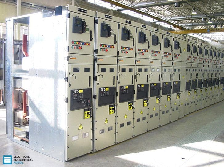
Electrical testing and commissioning of Metal-Clad switchgear is essential to the safe start for the first time, regardless of its size, type or industry. This article covers testing and start-up / commisioning procedures for all the components of medium voltage switchgear like circuit breaker, busbars, instrument transformers (current/voltage), disconnect and grounding switches etc.
1.1. Objective
To verify the physical condition and proper connections of bus bar.
1.2. Test Equipment Required:
- Insulation test (Megger)
- Micro ohmmeter
- High voltage tester
- Torque wrench
1.3. Test Procedure:
1.3.1. Mechanical Checks and Visual Inspection:
- Inspect switchgear and all components for any physical damage / defects.
- Check nameplate information for correctness.
- Inspect enclosures for proper alignment, foundation fixing, and grounding and vermin entry.
- Inspect all covers, panels’ section and doors for paintwork and proper fit.
- Check all the transport locks are removed.
- Check for smooth and proper movement of racking mechanisms, shutter, rollers, rails and guides.
- Check proper alignment of the primary and secondary contacts.
- Check operation of all mechanical interlocks.
- Check tightness of all bolted connections.
- Check for correct phasing connection of bus bar.
- Perform mechanical check and visual inspection for breaker / Contactor as per section.
- Perform mechanical check and visual inspection for instrument transformers as per section
- Perform mechanical check and visual inspection on all disconnect / grounding switches as per section.
1.3.2. Insulation Resistance Test:
It includes panel enclosure, busbar, CT and circuit breaker. The following precautions should be taken care, before starting the testing. A visual inspection will be made to ensure the surface dust and moisture has been removed from the component under test. Ensure the component is isolated from other connected system, which may feed back to other components or circuits not under test.
On testing, voltage shall be applied between one phase and other phases connected with ground, testing shall be repeated for other phases as mentioned above. Test voltage limits mentioned in table below:
| Rated voltage | Test voltage |
| 100-1000V AC/DC | 1000V DC |
| >1000 to <5000V AC | 2500V DC |
| > 5000V AC | 5000V DC |
1.3.3. Contact Resistance Test:
This test is to confirm the busbar joints are connected properly and verify the tightness. The test connection diagram is as shown in Figure below.
Limits //
The obtained results should be similar for all phases for each set of measurement. Other influencing factors to be considered, like length of the measured path, rating of the busbar, rating of CB, rating of CT and temperature.

1.3.4 High Voltage Test
To determine the equipment is in propercondition to put in service, after installation for which it was designed and to give some basis for predicting whether or not that a healthy condition will remain or if deterioration is underway which can result in abnormally short life.
Test Instruments Required //
- Calibrated AC Hi-pot test set for switchgear with leakage current indicator and overload protection.
- Calibrated DC Hi-pot test set for cables with leakage current indicator and overload protection.
1.4. Applicable Standard
IEC60298: – AC metal enclosed switchgear and control gear for rated voltage above 1KV to 52KV.
Resource: Procedures for Testing and Commissioning of Electrical Equipment – Schneider Electric
Related electrical guides & articles


Edvard Csanyi
Hi, I'm an electrical engineer, programmer and founder of EEP - Electrical Engineering Portal. I worked twelve years at Schneider Electric in the position of technical support for low- and medium-voltage projects and the design of busbar trunking systems.I'm highly specialized in the design of LV/MV switchgear and low-voltage, high-power busbar trunking (<6300A) in substations, commercial buildings and industry facilities. I'm also a professional in AutoCAD programming.
Profile: Edvard Csanyi

I should be exceedingly grateful if you could send me send me books, write up, journal on High Voltage switchgears, circuit breakers, power transformers and maintenance of substation.
useful information. thank u
Thanks Mr Edvard! for sharing such a useful knowledge. will you please also share Stability Test for busbars and GIS interlock tests. Thanks
Hi I would Like to know how to determine the contact resistance min value and max value acceptance level for 11kv (vcb) & 415v (acb) Switchgear. is there any formula to calculate the value. thanks in advance for the support
I want to know total testings n testing procedures for 11kv metalclad switchgear schineder made briefly
Thanks Mr.Edvard ,for always sharing useful and practical knowledge .
For contact resistance test why we need to inject 100 A? Is there any standard current values to inject? Pls guide me Mr.Edward
Hi Edward! For contact resistance test necessary to have a high current source. It is not a simple procedure, because of heavy instruments, power supply etc. I think it is not always necessary to do it on site. When must to do it? What are the reference resistance values? What are the permitted differences?
thanks for the useful article
I’m handling a project having Schneider GenieEvo 11KV Metal-Clad Switchgear. The consultant commented on Testing & Commissioning Method Statement asking as – FLASHOVER PROTECTION TO BE TESTED. Can you help me with the procedures, sketches, checks for this particular test. Or is it required to this as part of Site Test?
There is a procedure for testing such relays for arc flashing protection. Here is the procedure (in short):
Testing the arc flash sensors with the light only criteria operates the trip outputs of the main unit or I/O units for the protected zone. Testing the arc flash sensors with the light and current criteria, without an injected current, only generates an indication on the unit that protects the zone.
The indication of the fault is registered by the possible main unit and I/O unit.
Thanks for quick reply Dear Edvard. Was there is any block diagram any reference to commence the above test. Will be a very helpful step. Thanks again.
very helpful & informative
Glad you find it usefull!
thanks
Very useful technical articles and calculators both for designers and field personnel!!
Useful post thanks