1. Visual and Mechanical Inspection
- Compare cable data with drawings and specifications.
- Inspect exposed sections of cables for physical damage.
- Inspect bolted electrical connections for high resistance using one or more of the following methods:
- Use of a low-resistance ohmmeter in accordance with Section 1.2 above.
- Verify tightness of accessible bolted electrical connections by calibrated torque-wrench method in accordance with manufacturer’s published data or Table 100.12.
- Perform a thermographic survey.
(NOTE: Remove all necessary covers prior to thermographic inspection. Use appropriate caution, safety devices, and personal protective equipment.)
- Inspect compression-applied connectors for correct cable match and indentation.
- Inspect shield grounding, cablesupports, and terminations.
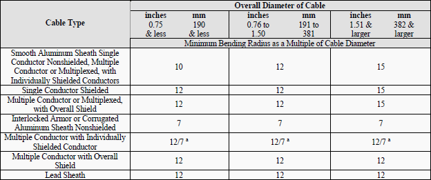
- Verify that visible cable bends meet or exceed ICEA and manufacturer’s minimum published bending radius.
- Inspect fireproofing in common cable areas. (**)
- If cables are terminated through window-type current transformers, inspect to verify that neutral and ground conductors are correctly placed and that shields are correctly terminated for operation of protective devices.
- Inspect for correct identification and arrangements.
- Inspect cable jacket and insulation condition.
** Optional test
2. Electrical Tests
- Perform resistance measurements through bolted connections with a low-resistance ohmmeter, if applicable, in accordance with Section 1.1.
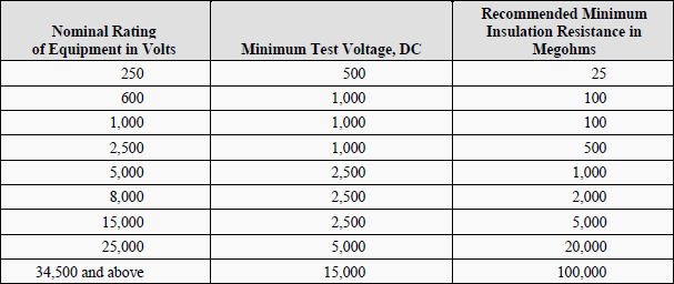
- Perform an insulation-resistance test individually on each conductor with all other conductors and shields grounded. Apply voltage in accordance with manufacturer’s published data. In the absence of manufacturer’s published data, use Table 100.1.
- Perform a shield-continuity test on each power cable.
- In accordance with ICEA, IEC, IEEE and other power cable consensus standards, testing can be performed by means of direct current, power frequency alternating current, or very low frequency alternating current. These sources may be used to perform insulation-withstand tests, and baseline diagnostic tests suchas partial discharge analysis, and power factor or dissipation factor. The selection shall be made after an evaluation of the available test methods and a review of the installed cable system.
.
Some ofthe available test methods are listed below:
.- Dielectric Withstand:
- Direct current (DC) dielectric withstand voltage
- Very low frequency (VLF) dielectric withstand voltage
- Power frequency (50/60 Hz) dielectric withstand voltage
- Baseline Diagnostic Tests:
- Power factor/ dissipation factor (tan delta):
- Power frequency (50/60 Hz)
- Very low frequency (VLF)
- DC insulation resistance:
- Off-line partial discharge:
- Power frequency (50/60 Hz)
- Very low frequency (VLF)
- Power factor/ dissipation factor (tan delta):
- Dielectric Withstand:
3. Test Values
3.1 Test Values – Visual and Mechanical
- Compare bolted connection resistance values to values of similar connections. Investigate values which deviate from those of similar bolted connections by more than 50 percent of the lowest value.
- Bolt-torque levels should be in accordance with manufacturer’s published data. In the absence of manufacturer’s published data, use Table 100.12.
- Results of the thermographic survey.
(NOTE: Remove all necessary covers prior to thermographic inspection. Use appropriate caution, safety devices, and personal protective equipment.) - The minimum bend radius to which insulated cables may be bent for permanent training shall be in accordance with Table 100.22.
3.2 Test Values – Electrical
- Compare bolted connection resistance values to values of similar connections. Investigate values which deviate from those of similar bolted connections by more than 50 percent of the lowest value.
- Insulation-resistance values shall be in accordance with manufacturer’s published data. In the absence of manufacturer’s published data, use Table 100.1.Values of insulation resistance less than this table or manufacturer’s recommendations should be investigated.
- Shielding shall exhibit continuity. Investigate resistance values in excess of ten ohms per 1000 feet of cable.
- If no evidence of distress or insulation failure is observed by the end of the total time of voltage application during the dielectric withstand test, the test specimen is considered to have passed the test.
- Based on the test methodology chosen, refer to applicable standards or manufacturer’s literature for acceptable values.
Tables
Table 100.12.1
Bolt-Torque Values for Electrical Connections
– US Standard Fasteners (a)
– Heat-Treated Steel – Cadmium or Zinc Plated (b)

a) Consult manufacturer for equipment supplied with metric fasteners.
b) Table is based on national coarse thread pitch.
Table 100.12.2
– US Standard Fasteners (a)
– Silicon Bronze Fasteners (b, c)
Torque (Pound-Feet)

a) Consult manufacturer for equipment supplied with metric fasteners.
b) Table is based on national coarse thread pitch.
c) This table is based on bronze alloy bolts having a minimum tensile strength of 70,000 pounds per square inch.
Table 100.12.3
– US Standard Fasteners (a)
– Aluminum Alloy Fasteners (b, c)
Torque (Pound-Feet)

a) Consult manufacturer for equipment supplied with metric fasteners.
b) Table is based on national coarse thread pitch.
c) This table is based on aluminum alloy bolts having a minimum tensile strength of 55,000 pounds per
square inch.
Table 100.12.4
– US Standard Fasteners (a)
– Stainless Steel Fasteners (b, c)
Torque (Pound-Feet)

a) Consult manufacturer for equipment supplied with metric fasteners.
b) Table is based on national coarse thread pitch.
c) This table is to be used for the following hardware types:
- Bolts, cap screws, nuts, flat washers, locknuts (18-8 alloy)
- Belleville washers (302 alloy).
Tables in 100.12 are compiled from Penn-Union Catalogue and Square D Company, Anderson Products Division, General Catalog: Class 3910 Distribution Technical Data, Class 3930 Reference Data Substation Connector Products.
Table 100.1
Insulation Resistance Test Values Electrical Apparatus and Systems

In the absence of consensus standards dealing with insulation-resistance tests, the Standards Review Council suggests the above representative values. Test results are dependent on the temperature of the insulating material and the humidity of the surrounding environment at the time of the test.
Insulation-resistance test data may be used to establish a trending pattern. Deviations from the baseline information permit evaluation of the insulation.
Table 100.22
Minimum Radii for Power Cable
Single and Multiple Conductor Cables with Interlocked Armor, Smooth or Corrugated Aluminum Sheath or Lead Sheath

a. 12 x individual shielded conductor diameter, or 7 x overall cable diameter, whichever is greater.
Resource: STANDARD FOR ACCEPTANCE TESTING SPECIFICATIONS for Electrical Power Equipment and Systems (NETA 2009)


What is the recommended test procedure for testing load bank cables?
Which standard is requesting the dielectric withstand test to be done after installation?
what is the minimum length of cable for which HV test should be done?
If its a short cable between Transformer to switchgear (less than 100 mtr), it HV test applicable or only IR will suffice?
whatis the standard for the insulation test for the cable:
IEC60502-2-2014-6~30kv Cables
Power cables with extruded insulation and their accessories for rated voltages
from 1 kV (Um = 1,2 kV) up to 30 kV (Um = 36 kV) –
Part 2: Cables for rated voltages from 6 kV (Um = 7,2 kV) up to
30 kV (Um = 36 kV)
IEC 62067
Power cables with extruded insulation and their accessories for
rated voltages above 150 kV (Um = 170 kV) up to 500 kV (Um =
550 kV)
Guys pls send me , MV&LV cables in testing & commissioning method statements , its very urgemts
[email protected]
Is there any latest techniques to identify the faults in EHV cables in the shortest possible time
What is the Difference Between Capacitance Charging Current And Leakage Current in Cable ? During High votage
What is the purpose of shield testing?
How to do the shield testing?
i need the answer please send me as soon as possible.
What is the permissible leakage current value for a 11kv cable.If there any formula for calculating leakage current, (cable rated voltage -8.7 to 15 kv, 2070 meter length,ac hi-pot test kit, applied volt: 27 kv )
If you can give me a standard scope to do the test with contractor
Good job done. Thank you very much
hai someone tell me about 11kv transformer Pressure test procedure.
Any one please explain the Hi pot (Pressure Test) testing procedure for 3 core 70 sq.mm Copper MV Cable
we need to apply 1.414 times (11*1.414=15545 volts dc) of voltage between phase to phase
or between phase to earth.
Hi
Need some advise on doing some end to end phasing test on 3km 110kv cable, the cable impedance is 34ohms, one end of line is overhead and it then goes underground and going overhead again, overhead cable one side is about 3km then undergrond of 3kms and overhead again for 30kms , can we use a generator to inject current into this cable. Or The capacitive inrush will defeat the generator…..
Our client has required us to perform tests to prove that metallic screen of 11kV cables are capable of sustaining the specified earth fault current . Can you please elaborate this . Who will perform these test? How can these tests can be performed.
Hello Syed Kumail Abid, I didn’t see any replies on your question but I’d be grateful to know what advice you were given. It is my understanding that the metallic screen on 11kV cables is not there to carry fault current. The screens are to control the electrical stress produced under load. Whilst it is true that the screen must be connected to earth in order to function correctly, it is not designed to carry any significant load. Its only other purpose is to act as an electrical protection device guarding against punctures of the cable. This would produce a localised short circuit between conductor and the earthed screen, which should immediately operate the protection device.
Hi Syed, Stephen. Most 11KV screened cable is designed to carry fault current. OIexs standard 11kV 3C HV cable is rated for 10kA.
Good job,thanks
Thank you…..
good job..this is a great way of having info at your fingertips.
Great article as always. Take a look at our website or contact Thorne and Derrick for a wide range of products related to MV/HV cables and cable joints.
Dear
I tested a Mv cable (5kv) first i applied insulation test on 5kv result was 218 Gega ohm.when VLF applied .test failed on 4kv .i am worry about megger test .i am thinking megger test is not reliable .please suggest ,
best regards
good job..this is a great way of having info at your fingertips
Thank You :)
thanks for this