
Estimated Study Time: 5 minutes
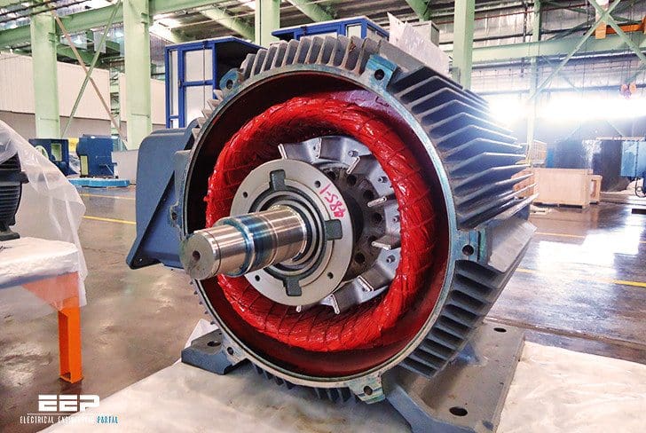
Scope Of Motor Testing
It should be noted that the scope of motor testing depends upon the motor type and size, this being indicated on the inspection forms.
Motor vibration shall be measured in a tri-axial direction, i.e.:
- Point x axis – side of bearing housing at shaft height
- Point y axis – top of bearing housing
- Point z axis – axial of bearing housing at shaft height
The measurements shall be carried out with an instrument conforming to ISO 2954 (10-1000 Hz frequency range). With the motor at normal operating temperature, the vibration velocity shall not exceed 2.8 mm/s RMS, or 4 mm/s PEAK, in any direction.
For bearings fitted with proximity probes, the unfiltered peak-to-peak value of vibration (including shaft ‘run-out‘) at any load between no load and full load, shall not exceed the following values:
- 50 µm for two-pole motors
- 60 µm for four-pole motors
- 75 µm for six-pole or higher motors

Bearing temperature rise limits following a ‘heat run’ of 3.5 – 4 hours are as follows:
Rolling bearings:
- Outer ring measurement max. 90 °C
- Temperature rise from ambient max. 50 °C
Sleeve bearings:
- Oil temperature max. 90 °C
- Bearing temperature rise by RTD max. 50 °C
- Lub. oil temperature rise from ambient max. 30 °C (for forced lub. oil systems).
This may be measured and rectified during installation or detected during running by the loosening of each holding-down bolt in turn while measuring motor vibration.
Motor ‘Soft Foot’ Condition
‘Soft feet’ are those which do not have solid flat contact with the base prior to the tightening of the holding-down bolts; one or more feet may be ‘soft’ as shown in Figures 1 to 3.
The profile of the foot contact area may be as shown in Figures 4 to 6.

- Figure 1 – Machine resting on 3 feet, foot 4 is raised or ‘soft’
- Figure 2 – Machine resting on diagonal formed by feet 3 and 4, feet 1 and 4 are ‘soft’
- Figure 3 – Bottoms of all 4 feet are not parallel with base, feet 3 and 4 are ‘soft’

NOTE: Re-machining of rotor feet is required in Figures 4 and 5; temporary use of wedge-shaped shims may be acceptable (maintenance).
Forms
Form 14 – Inspection of electric motor – Cage-induction type (incl. control unit)
")
Form 4 – Inspection of Switching Units – HV Switchgear

Form 11 – Inspection Of Outgoing Unit – LV Switchboard

Reference: Field Commissioning and Maintenance Of Electrical Installations and Equipment Manual
Related electrical guides & articles


Edvard Csanyi
Hi, I'm an electrical engineer, programmer and founder of EEP - Electrical Engineering Portal. I worked twelve years at Schneider Electric in the position of technical support for low- and medium-voltage projects and the design of busbar trunking systems.I'm highly specialized in the design of LV/MV switchgear and low-voltage, high-power busbar trunking (<6300A) in substations, commercial buildings and industry facilities. I'm also a professional in AutoCAD programming.
Profile: Edvard Csanyi

Very Helpful
Hi
It was very useful for me.
Please mention the the link of the Reference that you mentioned above for Form 14 – Inspection of electric motor – Cage-induction type (incl. control unit):
Reference: Field Commissioning and Maintenance Of Electrical Installations and Equipment Manual
Dear Sir,
We have planned to design a dual compressor 600 tonne Air conditioning plant. Each motor rating is 280 KW& Medium Voltage ( 6.6 KV). The motor is refrigerant cool.Please let me know site and factory commissioning tests as per the Indian Standard.
Thanks
Kishor kajrolkar
Hello
I ordered a 11-kW three-phase electromotor to make.
What level of inspection do I have during construction?
Which one of the factory tests is better to attend?
During factory acceptance test (FAT) min below to be witnessed –
1) No load & Full load current.
2) Max. current/ Thermal withstand limit of winding insulation.
3) Vibration (peak & RMS)
Level of Inspection during construction (SAT)-
1) Insulation resistance (IR) to be checked and shall be 100 Mega Ohm (MΩ) with 1000 V Megger.
2) Winding resistance shall be maximum of 2 Ω
3) Vibration 2 mm/s RMS and 5 mm/s Peak.
The information for testing and commissioning of motor was informative very useful.
Need checklist of Mechanical Sequence for motor Solo Run test.
Dears,
We have a medium voltage motor that has been relocated. Does this motor need a solo run?
Thanks,
Dear Sir
What is the recommended duration for the solo run test / no load test ?and please put your reference if any
Thanks
i need answer for same question….???
I have read your article its good and wish you could be sending me your newsletter. Thanks.
Dear Sirs, Greetings. This is a very useful article.Warmest Regds.
The Electrical Drive Motors are to be Diagonally earthed at two sides ( per B S Std.)The Reason is to Protect the Drives, !) For the Distribution of Leakage Currents,and 2) in case one gets disconnected/loosened due to Drive Vibrations.
Good day!
1(We have did solo run test to a squirrel cage induction motor at our construction site.
We have run the motor for 4hr and every 30 min current has measured.bo load current as per motor data sheet is 4 Amps but we got 0.9 amps on readings
Is there any problem.?kindly advise.
2)Is there any special procedure for vertical motor solo run test?If any international standard kindly advise.
Regards
Ratheesh
Dear Sir;
We are doing solo run test for the motors in our construction project.The value of no load current we are getting is not matching with the data sheet value.For example on data sheet the value mentioned is 9Amps but we are getting 11Amps.
Is there any problem for this?Any standard is available which is giving a guidline on this.
Thank you for your response.
Induction motor on general takes 30 to 40 percent of Full load current. There is not much difference between 9 Amp and 11 amp. Considering ideal voltage(415 V exact) it draws 11 amp. During construction site, voltage may varies. So in my view there is no problem at all.
What are the different conditions for measuring the vibrations of a synchronous motor.
Hi Edvard. Is this extracts from Shell DEP? I have seen the forms and some sketches from such documents.
please
could you tell me about turbo generator testing & commissioning procedure ??
Good Article. Can some one suggest the basic test to be carried out on induction motor if a motor is unservice,acceptableresistance value etc……
thanks for good article,, useful for commissioning and maintenance staff
Hi Edvard kindly some info related to verticalmotors
The problems facing in our Plant with LT motors
1.When we open motor for overhauling we find a lot of grease inside it even though nipples are provided for grease in and out,The frequency of greasing is also right.What may be the reason?
2.In vibration report mostly they say high frequency components in bearings and recommend us to grease.Is this a right procedure?
3.If we check resistance and inductance before rewinding and if we check after some months and if we find a variation in Resistance and Inductance what may be the reason?(Resistance we can say short or open in turns)
4.Why double grounding is needed for motors?(Is it just to maintain availability of one earthing even if other disconnects due to some problem)
5.If any information to vertical motors like vibration,IS standards please post
Hi Adipriya,
Please find some of the answers for your question.
1.When we open motor for overhauling we find a lot of grease inside it even though nipples are provided for grease in and out,The frequency of greasing is also right.What may be the reason?
It is basically the grease got lost its viscosity. It happens due to long running hours, over heat, may be high ambient, Etc.
3.If we check resistance and inductance before rewinding and if we check after some months and if we find a variation in Resistance and Inductance what may be the reason?(Resistance we can say short or open in turns) – Resistance value may increase becuase of its life. Littel variation in resistance and inductance doesn’t mater. You will see a big variation when you have a short inside.
4.Why double grounding is needed for motors?(Is it just to maintain availability of one earthing even if other disconnects due to some problem)
5.If any information to vertical motors like vibration,IS standards – Yes, you are right. It is for redundancy. nothing else. I think some standards (IS, IEC) requires doube earthing for safety.
Thank u sadha