
Estimated Study Time: 20 minutes
Testing and commissioning precautions
This article continues the series of articles dedicated to the erection, testing and commissioning of MV/HV switchgear by describing the most important precautions and recommendations in various procedures and steps. Starting from the wiring of low voltage command and signal cables, filling CBs with SF6 gas, special attention is given to testing and commissioning checks (visual, mechanical, electrical, operational and insulation resistance).
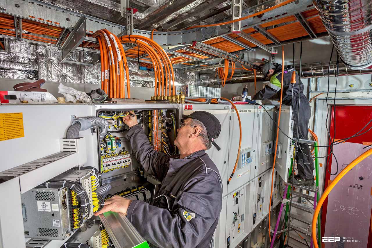
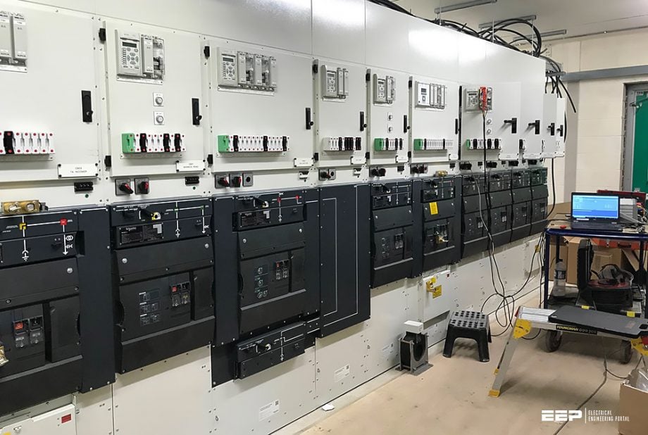 Guide to testing and commissioning of MV/HV switchgears (Wiring, final inspection and checks) - photo credit: NSS Ltd.
If you didn’t already, I highly recommended to read first: Guide to erection and commissioning of MV/HV switchgear – Inspection, installation and assembly (click here). Actions and procedures explained there start from scratch in explaining the testing and commissioning.
- Small Wiring And Connection Of LV Cables
- Filling With Insulation Medium
- Earthing of Switchgear
- Final Inspection
- Testing and Commissioning
- Final Commissioning / Load Testing
- Dos & Don’ts
1. Small Wiring And Connection Of LV Cables
Small wirings are auxiliary circuits such as tripping, closing, indicating, metering and protection CT/VT circuits. The CT circuit should be made to form a dosed circuit as dangerous voltages may develop under open circuit conditions and may even puncture the CT insulation.
It must be ensured that the ratings of CTs with meters, relays, etc. are matching. The auxiliary wiring should be neatly supported, and loose wires should be avoided as they may interfere with other devices. Refer to the schematic and wiring diagram and connect the required cables of auxiliary supply controls, metering and protection. Always use proper glands and lugs.
It is necessary to complete the small wiring connections of the panels to the adjacent cubicle and to connect external multi-core cables to the terminal blocks.
2. Filling With Insulation Medium
Depending upon the design of the switchgear, oil or SF6 gas is to be filled as an insulating medium. After drying out of the switchgear, proper oil level or proper pressure of SF6 gas needs to be maintained as per the manufacturer’s recommendations. In many designs, poles are filled with nitrogen gas above atmospheric pressure (1.5/2 times of the atmospheric pressure) to avoid breathing of moist air.
Similarly for air blast switchgear or switchgear having pneumatically operated mechanism, due care and attention should be given to joints in piping with air at pressure. Tests should be conducted to check for air leakage after installation in order to ensure correctness of such joints.
A thin soap solution can be used for checking air leakage.
3. Earthing of Switchgear
Earthing points provided in switchgear are to be connected with the station earth bar/earth grid. Measurements of earth impedance are made to ensure that no dangerous voltages can arise due to fault currents flowing in the earth conductors.
All equipment should be solidly and effectively earthed to the earth connection of the switchboards.
4. Final Inspection
After the switchgear erection has been completed, a final inspection is made covering various aspects of both indoor and outdoor switchgear. The details of this inspection are discussed below.
Related electrical guides & articles


Edvard Csanyi
Hi, I'm an electrical engineer, programmer and founder of EEP - Electrical Engineering Portal. I worked twelve years at Schneider Electric in the position of technical support for low- and medium-voltage projects and the design of busbar trunking systems.I'm highly specialized in the design of LV/MV switchgear and low-voltage, high-power busbar trunking (<6300A) in substations, commercial buildings and industry facilities. I'm also a professional in AutoCAD programming.
Profile: Edvard Csanyi
