


Estimated Study Time: 29 minutes
Transformer commissioning
This technical article discusses a comprehensive approach to conduct transformer commissioning successfully. The set of standards employed, test classes, and test sequence shall be identified beforehand. The pre-commissioning phase is vital in finding any issues prior to engaging in the commissioning process.
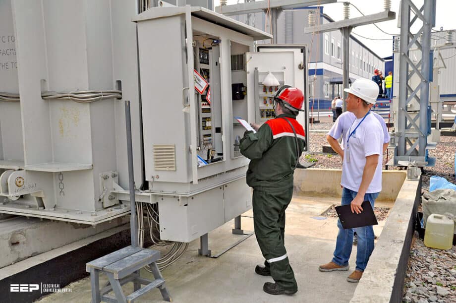 My worst experience in testing and commissioning power transformers
Delays are expected during the commissioning phase due to many reasons, but this can be enhanced substantially by imposing a systematic procedure. Moreover, few case studies are briefly discussed to shed light on some common problems that are likely to be encountered during the commissioning.
Some of these cases could have been avoided by following simple visual inspection, so it cannot be emphasized much to follow a well-written procedure.
The nominal rating specifications are not the only specifications that should be included, but also special ratings like impedance, sound level, or otherwise shall be considered in the test plan and formulated in the specifications.
It is vital to select the set of test plans and specifications of correct test levels that suit the transformer application so as to have an overall reliable power system.
Transformers are subjected to a number of test plans in order to achieve:
- Compliance with user specifications
- Quality and reliability assessment
- Design calculation verification
- Compliance with applicable industry standard
- ANSI standards for power transformers
- Classification of Tests
- Sequence of Tests
- Transformer Pre-Commissioning
- Transformer Commissioning:
- Case Studies
- Attachment (PDF) 🔗 Standards used for power transformers (PDF)
1. ANSI standards for power transformers
ANSI standards for power transformers are provided in the C57 series of standards. Power transformers, as well as distribution transformers general requirements, are given in the following two standards:
- IEEE C57.12.00: IEEE Standard General Requirements for Liquid-Immersed Distribution, Power, and Regulating Transformers
- IEEE C57.12.90: IEEE Standard Test Code for Liquid-Immersed Distribution, Power, and Regulating Transformers; and Guide for Short-Circuit Testing of Distribution and Power Transformers (ANSI)
There are several other standards in the ANSI C57 series for transformers that cover certain specific products and special applications. They also include guides, recommended practices, and tutorials. Indeed, these documents are of great importance for readers who need detailed information on power and distribution transformers testing.
The standards mentioned above are very important references because they serve as an effective communication medium between manufacturers and users. They identify critical features, provide minimum requirements for safe and reliable operation, and serve as valuable references of technical information.
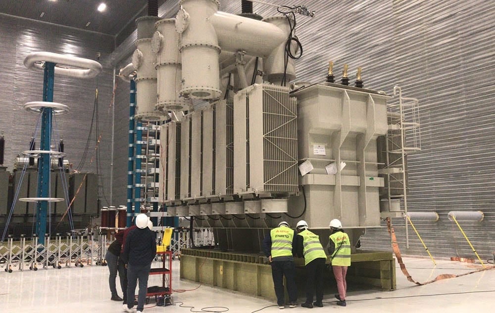
2. Classification of Tests
Power transformers tests are classified according to ANSI and IEEE standards into routine tests, design tests, and other tests. Other tests are applied to ensure the transformer quality measures throughout the transformer production cycle stages. Power transformer test categories are listed in Table 1.
Table 1 – Transformer test categories
| No. | Transients |
| 1 | Lightning impulse: – Full wave – Chopped wave – Steep wave |
| 2 | Switching impulse |
| No. | Low (Power) Frequency |
| 1 | Applied voltage |
| 2 | Single-phase induced |
| 3 | Three-phase induced |
| 4 | Partial discharge |
| No. | Tests of Performance Characteristics |
| 1 | No-load loss |
| 2 | Excitation current % |
| 3 | Load loss |
| 4 | Impedance % |
| 5 | Zero-sequence impedance |
| 6 | Ratio test |
| 7 | Short-circuit test |
| No. | Thermal Tests |
| 1 | Winding resistance |
| 2 | Heat run test: – Oil rise – Winding rise – Hottest-spot rise |
| 3 | Overload heat run |
| 4 | Gas in oil |
| 5 | Thermal scan |
| No. | Other Transformer Tests |
| 1 | Insulation capacitance and dissipation factor |
| 2 | Sound-level tests |
| 3 | 10-kV excitation current Megger |
| 4 | Core ground |
| 5 | Electrical center |
| 6 | Recurrent surge |
| 7 | Dew point |
| 8 | Core loss before impulse |
| 9 | Control-circuit test |
| 10 | Test on a series transformer |
| 11 | LTC tests |
| 12 | Preliminary ratio tests |
| 13 | Test on bushing CT |
| 14 | Oil preservation system |
The stage at which these tests are performed differ; some tests are applied before assembling the core and coil inside the tank, and some tests are performed after fully assembling the transformer and make it ready for final testing. This final testing term is not really final testing, as additional tests are performed just before shipment besides commissioning tests at customer sites.
NOTE! In all of these tests, the test levels and the accept/reject criteria are of prime importance in the jointly developed test plan between the manufacturer and the transformer client.
3. Sequence of Tests
The standardized documents specify the sequence in which these tests are performed. An example of a test sequence is as in Table 2 below.
Table 2 – Transformer sequence of tests
| No. | Tests Before Tanking |
| 1 | Preliminary ratio, polarity, & connection of the transformer windings |
| 2 | Core insulation tests |
| 3 | Ratio and polarity tests of bushing-current transformers |
| No. | Tests After Tanking (Final Tests) |
| 1 | Final ratio, polarity, and phase rotation |
| 2 | Insulation capacitance and dissipation factor |
| 3 | Insulation resistance |
| 4 | Control-wiring tests |
| 5 | Lightning-voltage impulse tests |
| 6 | Applied-voltage tests |
| 7 | Induced-voltage tests & partial-discharge measurements |
| 8 | No-load-loss & excitation-current measurements |
| 9 | Winding-resistance measurements |
| 10 | Load-loss & impedance-voltage measurements |
| 11 | Temperature-rise tests (heat runs) |
| 12 | Tests on gauges, accessories, LTCs, etc. |
| 13 | Sound-level tests |
| 14 | Other tests as required |
| No. | Tests Before Shipment |
| 1 | Dew point of gas |
| 2 | Core-ground Megger Excitation-frequency response test |
| No. | Commissioning Tests |
| 1 | Ratio, polarity, & phase rotation |
| 2 | Capacitance, insulation dissipation factor, & Megger tests |
| 3 | LTC control settings check |
| 4 | Test on transformer oil |
| 5 | Excitation-frequency response test |
| 6 | Space above the oil in the transformer tank |
4. Transformer Pre-Commissioning
The commissioning stage is anteceded by the pre-commissioning stage to prove that new transformers have been properly shipped and correctly erected and installed.
Generally, all electrical equipment types must be tested in the factory to generate the so-called Site Acceptance Test (SAT). The pre-commissioning testing is conducted to prove that:
- No equipment was subjected to any damage during transportation
- All equipment types have been installed correctly
- Equipment is working in harmony with other equipment as per specifications
- Protection and control schemes function in accordance with relevant specifications
- Equipment is adjusted as per approved settings
- Safe installation to energize equipment (very important!)
A procedure is required to check the complete readiness of the contractor prior to the pre-commissioning tests and to prepare for the commissioning tests.
This procedure has to outline the project (transformer) readiness for the commissioning tests, the contractor is fully equipped and ready from all aspects to conduct the commissioning tests, and the time of witnessing the pre-commissioning tests is at minimum duration with high-quality performance.
Transformer pre-commissioning tests and after-receipt checks you MUST perform
A joint inspection that involves the contractor and the client is mandated, and the elements of such an inspection could be viewed in Figure 1.
Moreover, the procedure shall describe at least the following:
- Project management structure and responsibilities
- Documents needed to commence the commissioning phase
- Site instruction records issuance
- Safety coordination & meeting
- Technical problem reporting
- Time and quality management
- Uncontrollable project delay form
- Readiness of energization report
- Final pre-commissioning reporting and contractor evaluation
- Fault report
- Implementation & improvement
It is quite necessary to prescribe a joint procedure with the contractor to facilitate the commissioning process. Besides the procedure described above, some documents must be submitted before proceeding to the transformer commissioning phase, especially for power transformers. These documents in conjunction with the agreed-upon procedure minimize the possibility of having some inspection activities gone unnoticed.
Rarely do you find an organization that utilizes these instructions fully since it is time-consuming and many contractors do not abide by such a procedure!
This might be true for small projects and transformers, but it pays off for complicated projects and large power transformers. A simple risk assessment tool could be used to show the impact of having a messy commissioning process to justify formulating a thorough and detailed pre-commissioning/commissioning procedure.
Related electrical guides & articles








Salem Alshahrani
Electrical engineer (BEE & Meng). Specialized in substation design, especially in LV/MV switchgears and transformers. Passionate in power system planning, analysis, and stability studies.Profile: Salem Alshahrani