
Estimated Study Time: 12 minutes
Understanding the ground system
First of all, it is extremely important that the operator/engineer understand the ground system that is being tested. The clamp-on measurement works well in many situations, but it has limitations and is not applicable in some configurations.
 8 applications of testing ground system using clamp-on tester
Clamp-on ground testing is a relatively new method of determining the quality of a ground system. It’s actually recommended to use it on sites where there are multiple grounds placed in parallel. This article does not explain the theory behind clamp-on testing, since this was earlier explained here.
In this technical article, we will look at eight different types of applications and outline whether the clamp-on method is viable or not (and why):
- Utility Poles/Service Entrance or Meter
- Street Lighting
- Lightning Protection
- Street Cabinets
- Telephone Pedestals
- Cell Towers (applications with buried ground ring)
- Pad Mounted Transformer
- Pole Mounted Transformer
1. Utility Poles/Service Entrance or Meter
The more parallel earths in series with the electrode under test, the nearer the measurement will be to the actual earth resistance value. Utility poles (see Figure 1) are an ideal application for the clamp-on method.
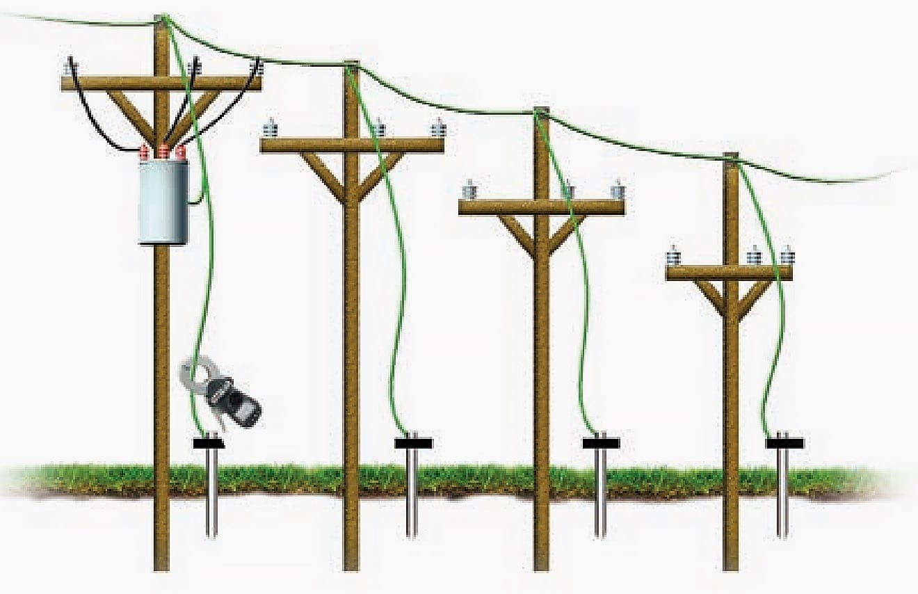
The earth systems on utility poles have many parallel ground connections making this a perfect location for using the clamp-on method. Each pole has a ground electrode to maintain fault and lightning protection, and pole mounted transformers have two electrodes on star configured systems.
Another related application is to test the ground electrode resistance on a service entrance or meter (see Figure 2 below). Here, there is the possibility of multiple earth paths, two electrodes, or maybe connection to a water pipe, so take care to identify the best positions to make a measurement.
Sometimes it is best to clamp the electrode itself below where the earth connections are made.

2. Street Lighting
A similar application to utility pole electrodes is street lighting. The cable running to each street light’s electrode may be clamped, but remember to clamp the correct side of the grounding conductor as shown below in Figure 3.

3. Lightning Protection
Another ideal application for the clamp-on test method is to test ground electrodes on lightning protection. Lightning protection on any building is only as effective as the quality of its grounding.
Electrodes are normally placed at each corner of a building with extra electrodes between on larger buildings. The conductors used are typically copper tapes up to 50 mm wide.
The following figure shows a typical lightning protection circuit where a clamp-on ground tester is clamped around the electrode.
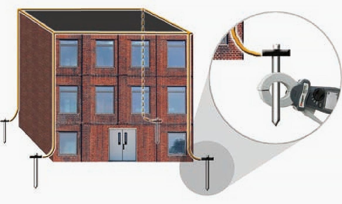
In many cases this is difficult because the electrode is buried in a small pit.
In addition, many lightning protection down tapes are fitted with removable links to allow the application of a two-wire continuity test. These removable links, often referred to as ‘jug handles’, are time consuming to remove, but make ideal locations to use a clamp-on tester.
Many lightning protection systems on factory buildings, especially in European countries, use lightning receptors mounted at regular intervals on the roof. These receptors are all interconnected as shown in the following figure.
This approach further decreases the series resistance of the parallel earth path, meaning the measured value is even closer to the true earth resistance of an electrode under test.
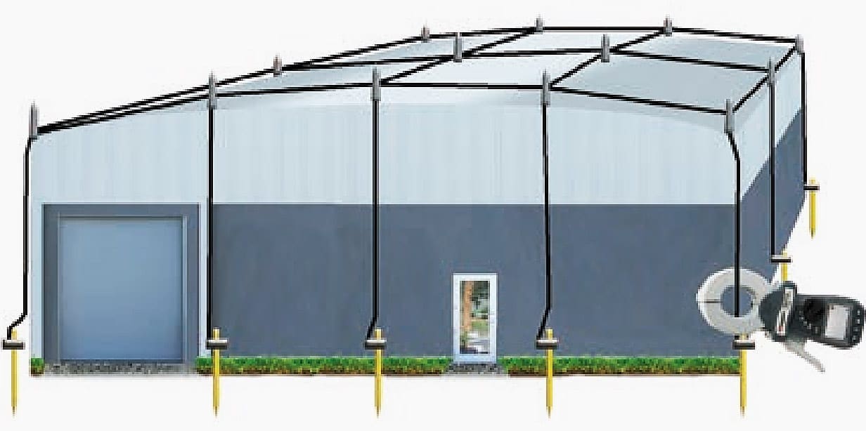
Remember there could be other connections to the lightning protection system. The user must remember to clamp around the tape below all connections. Otherwise the ground electrode will be tested in parallel to any other paths to earth. There may be connections to external metal work such as metal balconies and hand rails.
These must also be above the point where the clamp-on tester is clamped. Remember the importance of a visual inspection as well. With the price of copper, grounding tapes can be cut and stolen.
Depending where the tape is cut, and how the system is linked, the instrument could return a good, but false, reading.
4. Street Cabinets
Another application is to test the ground electrode installed inside primary cross-connection points, sometime called street cabinet-flexibility points (see Figure 6 below).
In this application there may not be more than two parallel earth paths in series with the electrode. However, based on the math, if the clamp-on ground tester provides a measurement below 25Ω, then the electrode must certainly be below 25Ω.

5. Telephone Pedestals
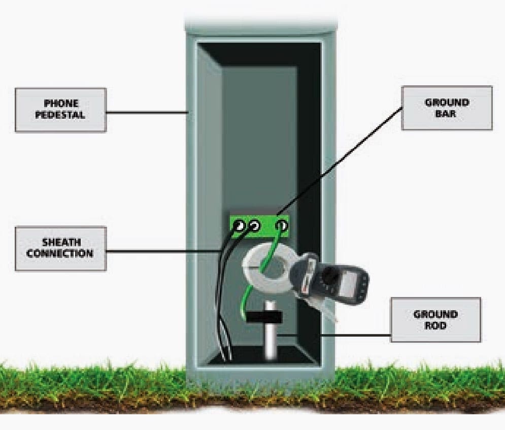
Telephone pedestal ground electrodes can be tested using the clamp-on method. Cable sheaths are all connected to a ground bar, which in turn is connected to the ground electrode.
The clamp-on can be placed around the cable connecting the ground bar to the electrode to perform a test. If access is difficult a temporary extension cable can be fitted to facilitate fitting on the clamp-on tester.
6. Cell Towers (applications with buried ground ring)
A ground resistance measurement cannot be made if the rods are linked together by a ring that is buried beneath the soil. This type of configuration, which is common in cell towers, allows access somewhere above the ring.
Cell towers are grounded at the base, with each guy wire grounded and all of them connected together in a ring of grounds.

If the operator clamps around the head of one of the guy wire grounds, the test current will simply complete the circuit in the ground ring and not through the soil. The test current circulates through the conductor that connects the individual elements (ground rods) that comprise the ring.
As such, the clamp-on ground tester will not be measuring the quality of the ground system. The reading will actually be a reading of the resistance of the “loop”.
This measurement does allow the operator to verify the connections beneath the soil.
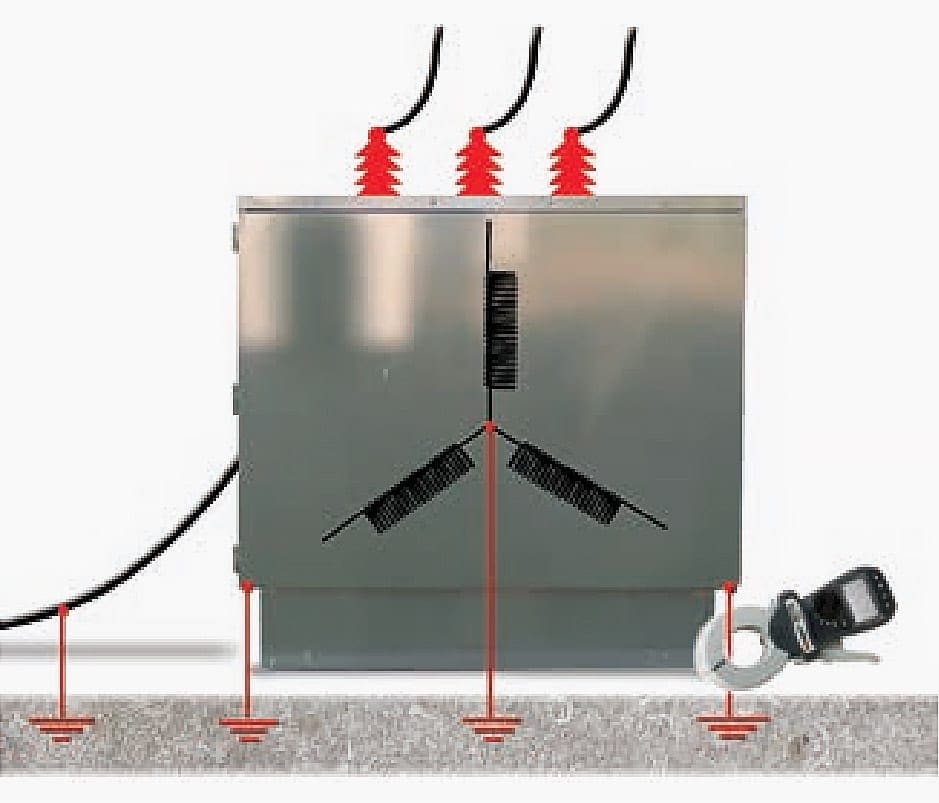
7. Pad Mounted Transformer
Pad-mounted transformer ground electrodes can be verified using the clamp-on method. However, sometimes there are a number of connections to the same electrode so the user may have to clamp around the electrode itself below the connections.
Should all these connections be to a large buried ground mat this measurement would then become a continuity measurement because the test loop will not include an earth path.
8. Pole Mounted Transformer
Remember the golden rules of clamp-on testing, “there must be a loop resistance to measure”! There are some occasions with utility poles where that loop does not exist, at least not where you want it to be anyway.
The figure below illustrates a system with a star-delta transformer mounted on a pole with two sets of electrodes.
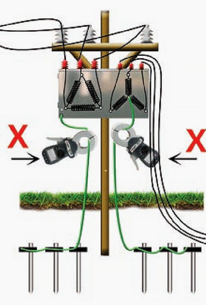
Neither set of electrodes are connected to an overhead earth cable. One is connected to the metal case of the transformer, and the other is connected to the star point of the LV secondary winding.
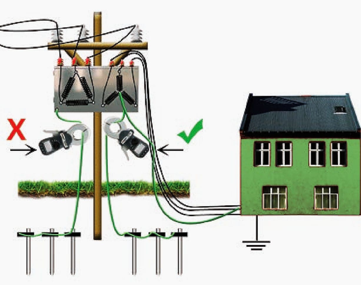
In contrast, in the graphic below, there is a connection to local distribution and its local ground system. This means we now have an earth loop to measure and a measurement may be taken.
However, remember the resistance measurement taken is a combination of the two earths in series.
A measurement of 40Ω will not mean each electrode system is below 25Ω of course, one could be 10Ω and the other 30Ω. If the measurement is, for example, 10Ω then we know we are going to be okay.
Reference // Guide to Clamp Ground Testing by MEGGER
Related electrical guides & articles


Edvard Csanyi
Hi, I'm an electrical engineer, programmer and founder of EEP - Electrical Engineering Portal. I worked twelve years at Schneider Electric in the position of technical support for low- and medium-voltage projects and the design of busbar trunking systems.I'm highly specialized in the design of LV/MV switchgear and low-voltage, high-power busbar trunking (<6300A) in substations, commercial buildings and industry facilities. I'm also a professional in AutoCAD programming.
Profile: Edvard Csanyi

Its helpful thank you for your inspiration
Helpful Details
I’m trying to get get clear idea of the best ground tester and testing method use for test ground at cell towers.
Your “EEP” portal is good and consisting practical data for all engineer
thanks your effort.
FERHAT M.SAVTEKIN (B.No;1102)
KAP5 Senior Electric Engineer
Please I have being following you for sometimes now. I really enjoying your scripts. And I want you to mentoring me so that I will become like you .Thank you.
perfect
thanks