
Estimated Study Time: 3 minutes
Earth-fault protection
Purpose of the measurement
The zero-sequence impedance is usually measured for all star-connected windings of the transformer. The measurement is carried out by supplying a current of rated frequency between the parallell connected phase terminals and the neutral terminal.
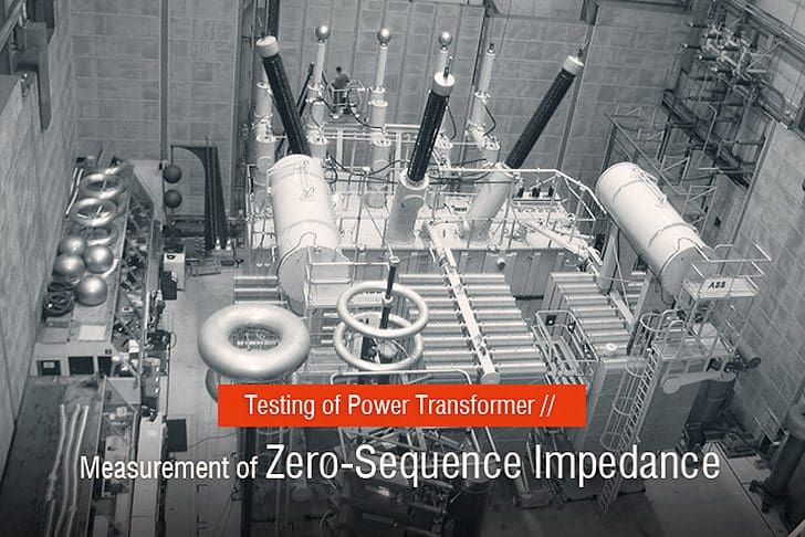
The zero-sequence impedance per phase is three times the impedance measured in this way. The zero-sequence is needed for earth-fault protection and earth-fault current calculations.
Measuring circuit and performance of measurement
Circuit for zero-sequence impedance measurement in shown below, where:
- G1 = supply generator
- T1 = transformer to be tested
- T2 = voltage transformer
- T3 = current transformer
- P2 = voltmeter
- P3 = ammeter
- I = test current

The zero-sequence impedance is dependent on the current flowing through the winding. Usually the value corresponding to rated current IN is stated. This implies that the measurement is carried out with a test current of 3 x IN.
However, this is not always possible in practice since the current must be limited to avoid excessive temperature of metallic constructional parts.
The zero-sequence impedance is measured as function of test current, and when necessary the final result is obtained by extrapolation.
Test Result
The zero-sequence impedance is usually given as a percentage of the rated phase impedance.
When the transformer has a three-limb core and no delta-connecter windings, the zero-sequence impedance is about 30…60 %. When the transformer has a delta-connected winding, the zero-sequence impedance is 0.8…1.0 times the corresponding short-circuit impedance.
In the test report the zero-sequence impedance values at the principal and extreme tappings are stated.
Reference: Testing power transformers – ABB
Related electrical guides & articles


Edvard Csanyi
Hi, I'm an electrical engineer, programmer and founder of EEP - Electrical Engineering Portal. I worked twelve years at Schneider Electric in the position of technical support for low- and medium-voltage projects and the design of busbar trunking systems.I'm highly specialized in the design of LV/MV switchgear and low-voltage, high-power busbar trunking (<6300A) in substations, commercial buildings and industry facilities. I'm also a professional in AutoCAD programming.
Profile: Edvard Csanyi

I have 22/11 kv, 10 MVA Dyn11,transformer while magnetic balance testing the middle phase readings are abnormal can anyone suggest the remedies for achieving the MBT.
What do you mean with “abnormal reading”. You should never expect equal readings in the 3 phases
A 5 MVA, 66/11kV, YNzn11 transformer nameplate shows an ‘Impedance Voltage’ of 7.18%.
Would this value be determined by short-circuiting the secondary ( z ) phase terminals and increasing the primary side ( Y ) phase-phase voltage until rated current flows in the shorted secondary ? The dataplate does not show a value for zero sequence impedance.
How would the zero sequence impedance be measured ? Star points earthed / unearthed ?
Would the measurements be different when the primary terminals are shorted be different from when the secondary terminals are shorted ?
Zero Sequence Impedance test for Three/ Two winding Transformer Star(Py) -Star(Sy) – Delta ( Teritary Winding) to Find out parameter of H,L,&T and convert to 100MVA Rating.This calculation is very useful for Transformer HV SBEF protection Settings.
If a three winding Y-Y transformer is kept idly charged ( secondary open ), it is seen that considerably high zero sequence current flows in the transformer, whenever there appears some unbalance voltage due to fault in the system. Can some one explain why ?
Tranformer tank as secondary of the transformer core and draws much more current from primary under unbalanced voltage condition due to fault.
Dear Edvard,
It’s nice to be here and read this great article, and I have two questions.
first one is, if the star connected side is the LV side can I make this test?
second one is, if the transformer is star/star connection should I make the test for two HV/LV sides?
Thanks and Regards.
Helo,
..i have noticed that, in our 333MVA unit main transformer, YND11 , 400/15 KV, neutral point is solidly earthed.. do you know why? Cause, 15KV generator is high impedance grounded.. but 400 KV transformer also should have impedance grounded.. why it is solidly grounded?
To limit the fault current on application / consumer side, high impedance is provided so that protection can be achieved and damage can be minimized during fault condition.
Regarding 400kV side, being Extra High Tension voltage, higher sensitivity of ground fault current is considered, second, Solid grounding system does not allow neutral shift which may increase 1.732 time voltage of other phases during ground fault. this may further lead to damages of equipment.
good
Top Manufacturer of 3 phase control transformers in Maharashtra
I’m new on this community,
and this is my very first post.
I really appreciate your hard work .
Thank you for this
Information.
Control Power Transformers Mumbai India
I’m new on this community,
and this is my very first post.
I really appreciate your hard work .
Thank you for this
Information.
Top Manufacturer of Single phase control transformers in Mumbai
This is something I really wanted to read-up on, plus you gave some extra links for further reading.
Thanks for the resources!
Top Manufacturer of 3 phase control transformers in Mumbai
your article is very useful
I really appreciate your work.
thank you for this information.
Electrical and Electronic engineer in thirst of learning about power systems
Great …. What is the mehodology of earthing to be adopted when substations are located on different floors in a high rise building? If earthing system is TT, what are earthing conductors can be grouped like HT panel body, Transformer body, LV panel body, neutral side of transformer etc.
Would be grateful if you could throw some lights with some supporting documents.
I am located in Mumbai, India.
Thanks and Regards,
Venkat Iyer
Simply Thanks…
Explain with motor traction