
Estimated Study Time: 8 minutes
Circuit breaker releases / Tripping units
The main objective of circuit breaker tripping units and protective functions in general is to detect faults and to selectively isolate faulted parts of the system. It must also permit short clearance times to limit the fault power and the effect of arcing faults.
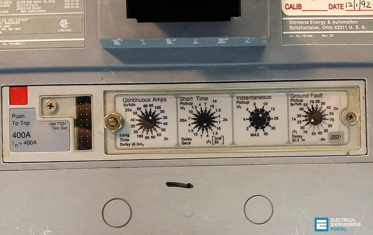 The Basics Of Circuit Breaker Tripping Units (on photo: Siemens molded case circuit breaker 'Sentron' Series; 400 Amp Frame - 400 Amp Trip)
The protective function of the circuit breaker in the power distribution system is determined by the selection of the appropriate release (see Figure 1). Releases can be divided into:
- Thermal-magnetic tripping units – TMTU, also called electromechanical releases and
- Electronic tripping units – ETU
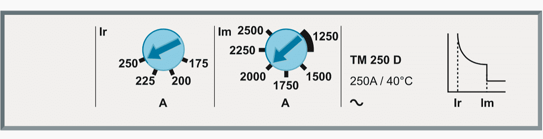
Thermal-magnetic tripping units //
The thermomagnetic trip unit consists of two parts:
The thermal trip unit – Made up by a bimetal thermal device which actuates the opening of a circuit breaker with a delay depending on the overcurrent value. This trip unit is intended for the protection against overloads.
The magnetic trip unit – Made up by an electromagnetic device, with fixed (fixed instantaneous trip) or adjustable (adjustable instantaneous trip) threshold, which actuates the instantaneous trip of the circuit breaker on a pre-determined overcurrent value (multiple of the In) with a constant trip time (about some tens of milliseconds). This trip unit is intended for the protection against short circuit.
Go back to CB tripping units ↑
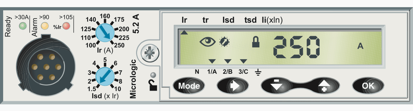
Electronic tripping units //
The electronic trip units instead use a microprocessor to process the current signal and operate the circuit breaker opening in case of fault. In addition to this, electronic tripping units offer more tripping criteria which are not feasible with electromechanical releases.
By digital processing of the signal, they provide the following protection functions:
- Long time-delay trip function (ANSI code: 51, AC time overcurrent relay);
- Short time-delay trip function (ANSI code: 51, AC time overcurrent relay);
- Instantaneous trip function (ANSI code: 50, instantaneous overcurrent relay);
- Ground-fault trip function (ANSI code: 51 N, AC time earth fault overcurrent relay).
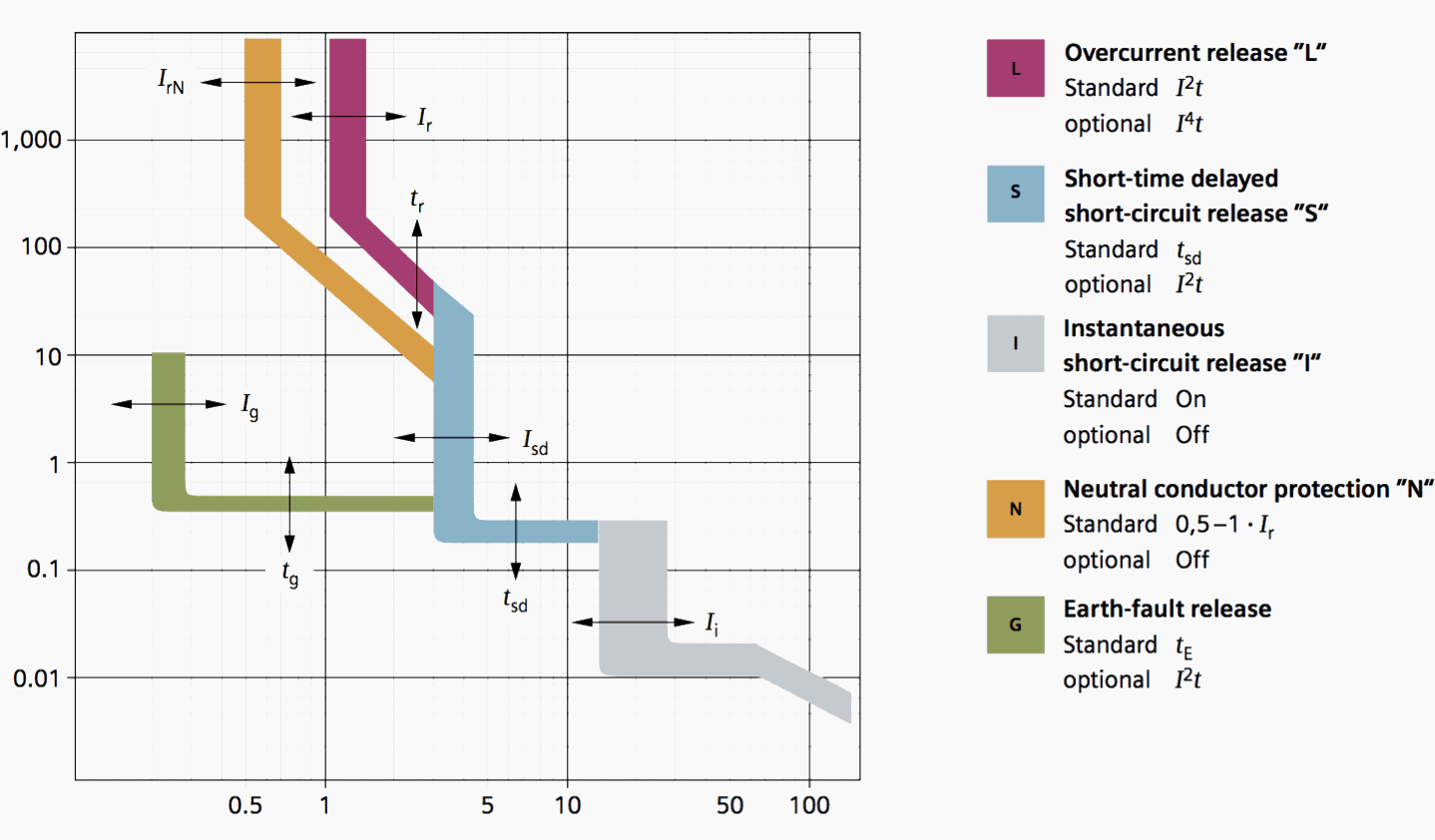
1. Overload protection
Designation: L (LT: long-time delay), previously a-release.
Depending on the type of release, inverse-time-delay overload releases are also available with optional characteristic curves.
The nominal pickup point where a circuit breaker trip unit detects an overload is at 1.075 times the selected ampere rating. After the circuit breaker has picked up, it will not trip until the delay determined by the long-time delay adjustment has been achieved.
2. Neutral conductor protection
Inverse-time-delay overload releases for neutral conductors are available in a 50% or 100% ratio of the overload release. The neutral must have specific protection if:
- It is reduced in size compared to the phases
- Nonlinear loads generating third order harmonics are installed
It may be necessary to cut off the neutral for functional reasons (multiple source diagram) or safety reasons (working with power off).
3. Short-circuit protection, instantaneous
Designation: I (INST: instantaneous), previously n-release
Depending on the application, I-releases can either be used with a fixed or an adjustable release current Ii as well as with a switch-off or non-switch-off function.
In circuit breakers with both short-time and instantaneous pickup, the instantaneous pickup will override the short-time pickup if the instantaneous pickup is set at the same or lower setting than the short-time pickup.
4. Short-circuit protection, delayed
Designation: S (ST: short-time delay), previously z-release.
To be used for a time adjustment of protective functions in series. Besides the standard curves and settings, there are also optional functions for special applications:
Definite-time overcurrent releases
For this “standard S function”, the desired delay time (tsd) is defined as of a set current value (threshold Isd) (definite time, similar to the function of “definite-time overcurrent-time protection (DMT)” at the medium voltage level).
Inverse-time overcurrent releases
In this optional S function, the product of I2t is always constant. In general, this function is used to improve the selectivity response (inverse time, similar to the function of “inverse-time overcurrent-time protection” at the medium voltage level.
5. Earth-fault protection
Designation: G (GF: ground fault), previously g-release.
Besides the standard function (definite-time) an optional function (I2t = current-dependent delay) is also available.
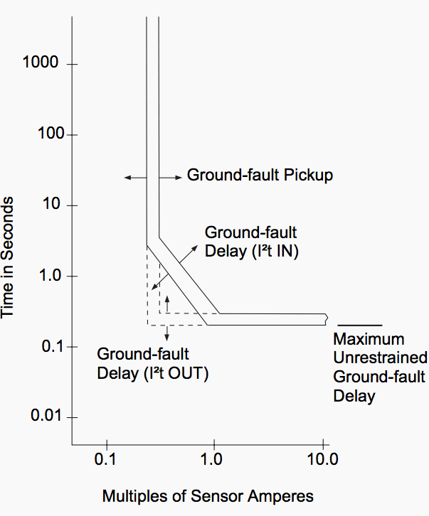
The ground-fault function is divided into pickup and delay components (see Figure 4). The pickup portion determines at what point the circuit breaker will begin detecting a ground fault.
The delay adjustment determines how long the circuit breaker will delay tripping after a ground-fault has been detected. It is supplied with both an “I²t IN” and an “I²t OUT” function on the circuit breakers.
In a circuit breaker with the ground-fault function, there is a maximum unrestrained ground-fault delay provided. This delay determines the maximum amount of time the circuit breaker will delay during a ground-fault condition when not restrained by a downstream breaker. The maximum delay is shown by a single line and stays constant for all ground-fault delay switch settings.
6. Fault-current protection
Designation: RCD (residual current device), previously also DI (differential current interrupter).
It detects differential fault currents up to 3 A, similar to the FI function for personal protection (max. 500 mA).
Go back to CB tripping units ↑
References //
- Planning of Electric Power Distribution – Technical Principles by SIEMENS
- Circuit Breaker Characteristic Trip Curves and Coordination by Schneider Electric
- Low Voltage Circuit Breakers complying with the Standards UL 489 and UL 1066 by ABB
Related electrical guides & articles


Edvard Csanyi
Hi, I'm an electrical engineer, programmer and founder of EEP - Electrical Engineering Portal. I worked twelve years at Schneider Electric in the position of technical support for low- and medium-voltage projects and the design of busbar trunking systems.I'm highly specialized in the design of LV/MV switchgear and low-voltage, high-power busbar trunking (<6300A) in substations, commercial buildings and industry facilities. I'm also a professional in AutoCAD programming.
Profile: Edvard Csanyi

Nice Article,I got more about MCCB tripping unit
Thank You so much
Suggestion: work a few examples using Figure 1 to teach the subscripts
Question: GE standard trip breakers, in 24 yo residential setting. What does “standard trip mean” in terms of trip current and time to trip, in a 45 amp 2-pole 240 V breaker?
Thank you for your informative website.
It’s my pleasure to meet you on this platform. I look forward to asking questions regarding Electrical Engineering Installation soon.
sir
i appreciate your work ,
u cover all thing in a single with easily understanding .
now i dont need to open any other pages .
thank sir
It was very interesting and keen to read more and ti understand more about air circuit breaker technology, safeties.
I so much appreciate this web site for the vital message given about engineering
Thanks
Hello, does series tripping is also incorporated in MV & HV Switch Gear?
Thanks and regards
My question is that how to set trip timing of ACB .what data take to set timing of ACB for setting time short circuit ,earth fault etc
I have 60A 480V 3PH 50HZ Square D breaker.
main (400/230, 50hr 3phase + pen) feeds two 3phase 5hp motors and with 25a mccb breaker feeds the sub panel 400/230a, 50hz.
the sub panel (400/230, 50hr 3phase + pen) feeds two AC with 1.7kva each , 20a single phase breakers and 1hp .4kava wtih 15a single phase breaker.
i have an issue with main breaker tripping when i start nay of the single phase equipment from the sub panel.
i don’t have main breaker trip when i start any equipment from the main panel.
any suggestion?
Dear,
I have 400 A breaker, please advises what its setting if it will connect the 250 kva 3ph transformer, and it LT Side circuit run 355 Amp each phase. Expect to have your valued reply soon.
A clear explanation for non-specialist, excellent language.
Nice article. If possible give an example ,how the selectivity is achieved.
What is writen is only valid for LV circuit breakers. MV and HV circuit breakers trips through na input signal of the protection relays to the tripping coil of the circuit breakers.
Common rated values for LV residual current devices are:
• High sensibility: 6; 10; 30 mA.
• Medium sensibility: 100; 300; 500; 1000 mA.
• Low sensibility: 3; 10; 30 A.