
Installation of Reactive Compensation
A car equipment manufacturer’s plant in Concord (Ontario, Canada) is supplied by a transformer rated at 2000 kVA – 27.6 kV / 600 V – Yy – Ucc = 5.23 %. It manufactures exhaust assemblies from steel plate using spot welders and seam welders.
 The Case Of Real Time Reactive Compensation (on photo: Schneider Elecric's protection part of complete reactive compensation solution 'Varset')
5 Problems encountered //
Problem #1Visual and nervous fatigue in personnel, due to the fluctuation in brightness of lamps (flicker) when welding equipment was in operation.
Problem #2Noise pollution and premature mechanical ageing of equipment caused by vibrations mainly in the transformer and the main switchgear when welding equipment was in operation.
Problem #3Inability to add equipment for fear that the installation would be overloaded (peak currents when welders were fired were greater that the nominal current of the main circuit breaker).
Problem #4Expansion of the installation would thus require substantial investment, either to upgrade the existing installation or to build a new power supply facility.
Annual penalties of 5 kEUR for exceeding the reactive power consumption limit (0.75 power factor).
Problem #5Defective parts caused by welding faults appeared at the end of the manufacturing process when the tubes are bent into shape. All these factors reduced company productivity.
Solutions // Measures taken
The measures taken during the operation of the welding equipment showed the following parameters (see Figure 1) //
- Nominal voltage of 584 V
- Voltage dips of 5.8 %
- Current peaks of 2000 A and
- Reactive power peaks of 1200 kvar
Figure 1 – Improvements due to the real time reactive compensator
| Improvements | Before | After | |
| Voltage | 584 | 599 | |
| Voltage Dip | Depth (%) | 5.8 | 3.2 |
| Duration (cycle) | 20 to 25 | 10 to 15 | |
| Current | Average | 1000 | 550 |
| Peak | 2000 | 1250 | |
| Reactive Power (kVar) | 600 to 1200 | 0 to 300 | |
| Power Factor | 0.75 | > 0.92 | |
The problems clearly stemmed from voltage fluctuations caused by the operation of welders with loads which vary rapidly and frequently and which consume significant reactive power.
A voltage dip of 6% produces a reduction of 12% (1-0.942) in the power available for welding. This was the reason for the large number of defective welds.
Standard devices for reactive power compensation use electromechanical contactors which cannot achieve the required response times. The operation of capacitor steps is deliberately time delayed to reduce the number of operations and avoid reducing the service life of the contactors through premature wear, as well as to enable the capacitors to discharge.
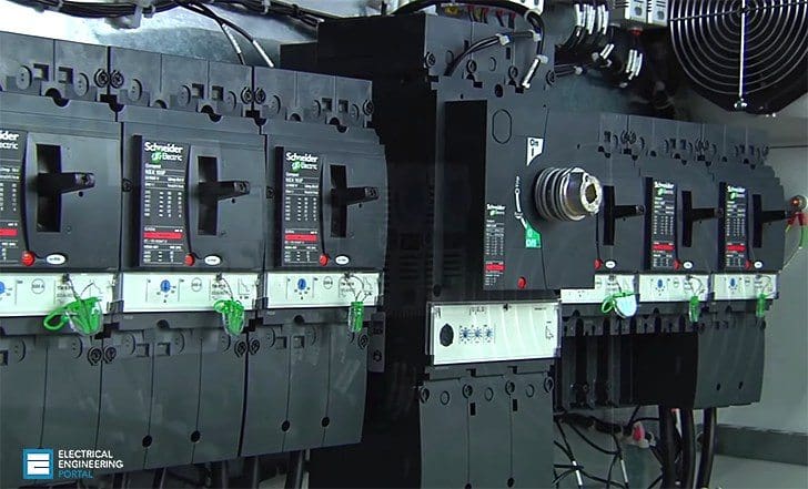
![Real time reactive compensator [a] principle, [b] practical implementation](https://electrical-engineering-portal.com/wp-content/uploads/2015/12/real-time-reactive-compensator.jpg)
Solution with Real time reactive compensator
The solution chosen was to connect a real time reactive compensator (see figure 2). This innovative device offers:
#1 Ultra-rapid reactive compensation of the variations in reactive power within one cycle (16.6 ms at 60 Hz), which is especially suitable for loads with rapid, large variations (welding machines, lifts, presses, crushers, motor starting, etc.);
#2 Transient-free switch through controlled switching, which is especially useful with loads which cannot withstand transient overvoltages (PLCs, computer systems, etc.);
#3 Increased service life of capacitors and contactors owing to the absence of moving mechanical parts and overvoltages
With reactive compensation of 1200 kvar it would be possible to minimise voltage dips, but 800 kvar was deemed sufficient to maintain the voltage at an acceptable level for all processes in the plant under all load conditions.
The results of implementing the solution are (see Figure 3) //
![Measurement of current, voltage and reactive power: [a] without compensation [b] with compensation](https://electrical-engineering-portal.com/wp-content/uploads/2015/12/measurement-of-current-voltage-reactive-power-compensation.png)
#4 A reduction in current peaks to 1250 A and the addition of loads without modification of the installation, with improved installation efficiency through reduction of joule losses;
#5 A reduction in reactive power peaks to 300 kvar and an increase in the power factor to over 0.92, thus avoiding power factor penalties.
#6 An increase in the nominal voltage to 599 V and a reduction in voltage dips to 3.2 % (see figure 2). This is a consequence of the increase in the power factor and reduction in the current amplitude (see figure 4).
Reference // Cahier Technique Schneider Electric no. 199 – Power Quality by Schneider Electric


happy to be part of this
Hello ,
First of all , I’m pleased to contact with u Mr.Edvard Csanyi.
I need for ur help to do my small researsh on ” REACTIVE -POWER-COMPENSATION , IN ELECTRICAL NETWORK ”
thanx.
Hi, can you provide more information about the actual RPC bank solution? IE how it achieves the real time compensation.
Similar questions to Tony, where is the information about cost and payback. I’d assume the system is installed on the LV side of the Transformer?
I found the article very misleading with the comparison before and after. Analytical approach appears to be biased towards sales rather than consumer benefit.
All the graphs seem to be intentionally misleading double time scale after and half amplitude scale rather than on the same scale.
There is no mention of cost before and after or payback period.
Lighting flicker can be regulated easily in other ways.
I also wonder if less costly passive PFC were considered for arc welding in lowering source ESR and providing circulating currents of stored energy.and isolation with VHF/UHF noise chokes.
capacitor will get overcharging how you arrange delay in reenergisation..
Great article, I’ve have seen similar voltage dips at industrial plants in the U.S. with large welding and motor loads.
nice article hope to get more from you . thanks …