
Estimated Study Time: 9 minutes
Nominal voltage 1kV – 35kV
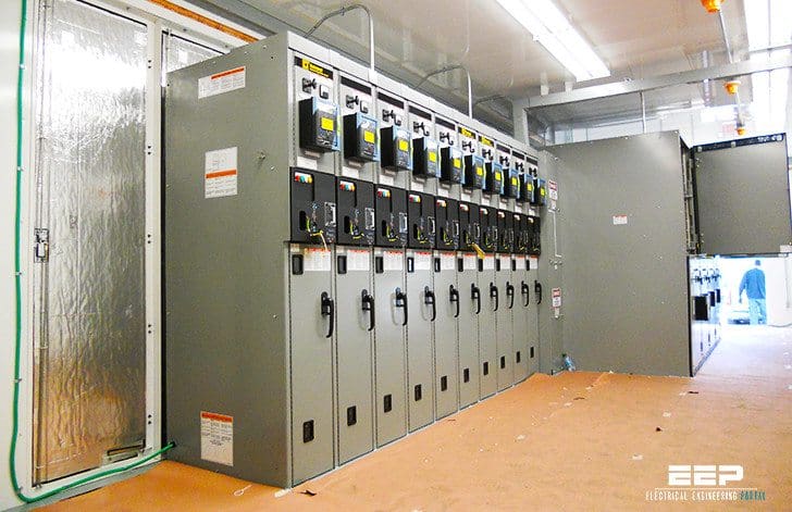
A consumer power substation with metering on medium voltage side is an electrical installation connected to a utility supply system at a nominal voltage usually between 1kV – 35kV, which for example may supply a single MV/LV transformer (exceeding generally 1250 kVA), several MV/LV transformers or one or several MV/LV secondary substations.
The single line diagram and the layout of a substation with MV metering depend on the complexity of the installation and the presence of secondary substations.
For example a substation may:
- Include one single room containing the MV switchboard, the metering panel, the transformer(s) and the low voltage main distribution board(s),
- Supply one or several transformers, each installed in a dedicated room including the corresponding main LV distribution switchboard
- Supply one or several secondary MV/LV substations.
Functions of the substation with MV metering
- Connection to the MV network
- MV/LV Transformers and internal MV distribution
- Metering
- Local emergency generators
- Capacitors
- LV main switchboard
- Simplified electrical network diagram
1. Connection to the MV network
Connection to the MV network can be made:
- By a single service cable or overhead line,
- By dual parallel feeders via two mechanically interlocked load-break switches
- Via a ring main unit including two load-break switches.

2. MV/LV Transformers and internal MV distribution
As well as for substation with LV metering, only oil-immersed and dry type cast-resin transformers are allowed with the same rules of installation. When the installation includes several MV/LV transformers and/or secondary MV/ LV substations an internal MV distribution network is required.
")
According to the required level of availability, the MV supplies to the transformers and the secondary substations may be made:
- By simple radial feeders connected directly to the transformers or to the secondary substations
- By one or several rings including the secondary MV/LV substations
- By duplicate feeders supplying the secondary MV/LV substations.
For the two latter solutions the MV switchboard located in each secondary substation includes two load break switch functional units for the connection of the substation to the internal MV distribution and one transformer protection unit, for each transformer installed in the substation. The level of availability can be increased by using two transformers operating in parallel or arranged in dual configuration with an automatic change over system.
3. Metering
The characteristics and the location of the VT’s and CT’s dedicated to the metering shall comply with the utility requirements.

The VT’s and CT’s are generally installed in the MV switchboard. A dedicated functional unit is in most of the cases required for the voltage transformers while the current transformers may be contained in the functional unit housing the circuit breaker ensuring the general protection of the substation.
4. Local emergency generators
Emergency standby generators are intended to maintain the power supply to the essential loads in the event of failure of the utility power supply. According to the energy needs an installation may contains one or several emergency generators.
The generators can be connected:
At MV level to the MV main substation (see Fig. B34).The generator(s) may be sized either for the supply of the whole installation or for a part only. In this case a load shedding system must be associated to the generator(s).

At LV level on one or several LV switchboards requiring an emergency supply. At each location, the loads requiring an emergency supply may be grouped on a dedicated LV busbar supplied by a local generator (see Fig. B32).

5. Capacitors
Capacitors are intended to maintain the power factor of the installation at the contractual value specified by the utility. The capacitor banks can be fixed or adjustable by means of steps.
They can be connected:
- At MV level to the main MV substation
- At LV level on LV switchboards.

6. LV main switchboard
Every MV/LV transformer is connected to a main LV switchboard complying with the requirements listed for substation with LV metering.

7. Simplified electrical network diagram

The diagram (Fig. B35) shows:
- The methods of connection of a MV/LV substation to the utility supply:
- Spur network or single-line service
- Single line service with provision for future connection to a ring or to dual parallel feeders
- Dual parallel feeders
- Loop or ring-main service
- General protection at MV level
- MV metering functions
- Protection of MV circuits
- LV distribution switchboard
- A MV Circuit breaker functional unit for the general protection of the substation
- A MV metering functional unit
- MV Functional units dedicated to the connection and the protection of:
- MV/LV transformers
- MV feeders supplying secondary substations
- MV capacitor banks
- Emergency generators
The general protection usually includes protection against phase to phase and phase to earth faults. The settings must be coordinated with the protections installed on the feeder of the primary substation supplying the installation.
Reference: Electrical Installation Guide 2015 – Schneider Electric (Download)
Related electrical guides & articles


Edvard Csanyi
Hi, I'm an electrical engineer, programmer and founder of EEP - Electrical Engineering Portal. I worked twelve years at Schneider Electric in the position of technical support for low- and medium-voltage projects and the design of busbar trunking systems.I'm highly specialized in the design of LV/MV switchgear and low-voltage, high-power busbar trunking (<6300A) in substations, commercial buildings and industry facilities. I'm also a professional in AutoCAD programming.
Profile: Edvard Csanyi

Good afternoon,
How much is the 11kv consumer substation?
How much is a 400v to 11kv transformer?
How much is a 400v mini substation?
How much is a 550v mini substation?
The LV connection between the tranformer and busbar system shown in your picture, should it be connected via a flexible link?
Interested so please inbox me more details..
Very good