
Estimated Study Time: 17 minutes
Motor protection circuit breaker (MPCB)
Application-specific variations of the MCCB, these breakers combine the short-circuit and isolation functionality of the MCCB with the motor overcurrent protection of a traditional overload relay. MPCBs are UL 489 Listed as circuit breakers and verified as motor overload relays.
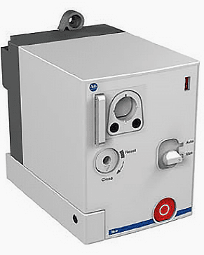
 Learn Design Of Motor Protection Circuit Breaker (on photo: Allen-Bradley 600V 140-CMN-4000 motor protection circuit breaker)
These devices are traditionally used in two component starter applications, with a contactor to control a motor load.
MPCB design
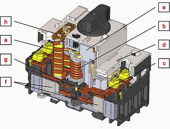
The parts of the motor protection circuit breaker detailed in Figure 1 are precisely coordinated so that the common tasks, the rapid disconnection of short-circuit currents and the dependable recognition of overloads, can be performed optimally.
The normal rated current as well as the short-circuit or the overload current flows from the incoming to the outgoing terminal of the circuit breaker through the magnetic and the thermal overload releases in series with the main contacts. Exactly the same current flows through all the functional modules. Unequal amplitude and duration of the currents in the different releases will obviously cause different individual reactions.
The main functional elements of a circuit breaker for motor protection:
- Thermal overcurrent release
- Electromagnetic overcurrent release
- Main contact system
[Covered sub-topics]
• Ultimate switching capacity and service switching capacity
• Let-through values
• Life span of circuit breakers
• Operational switching
• Auxiliary contacts and displays
• Shunt-trip and undervoltage releases
• Motor (remote) operators - Auxiliary switch position
- Switch latch
- Arcing chamber (de-ion plates)
- Plunger armature
- Differential trip slide
In larger circuit breakers (> approx. 100 A), electronic trip and communication modules are increasingly being used. These offer a high degree of flexibility with respect to the selection of application-specific parameters and support the integration of devices in superordinated control and management systems.
1. Thermal overcurrent release
The thermal overcurrent release of circuit breakers acts in the same way as those of thermal motor protection relays (bimetal overload relays) and are subject to the same standards if they are used for motor protection. Tripping is normally effected via the switch latch of the circuit breakers and results in the opening of the main contacts.
In the case of circuit breakers with thermally delayed overload releases and low setting currents (ca. < 20 A), the resistance of the circuit with the heating windings of the bimetal strips and the coil of the undelayed electromagnetic short-circuit triggers is comparatively large.
It may be so large that it damps any size of (prospective) short-circuit current to a value that the switch can still cope with thermally and dynamically and can hence also disconnect. Such circuit breakers are intrinsically safe against short-circuits.

Go back to Motor protection Elements ↑
2. Electromagnetic overcurrent release
In circuit breakers with motor protection characteristic overcurrents from a value of 10 … 16 times the upper scale setting immediately cause the electromagnetic overcurrent release to act. High efficiency motors may require higher magnetic trip levels.
The precise tripping value is either adjustable (matching for selectivity or various making current peaks in case of transformer and generator protection) or is determined by the design.
In circuit breakers for plant and line protection the tripping zone is lower. In small circuit breakers (usually < 100 A), the pole conductor is shaped in the form of a small coil. If a high overcurrent flows through these coils, a force acts on the armature enclosed by the coil. This armature unlocks the loaded switch latch that releases the stored spring energy and hence opens the main contacts and disconnects the overcurrent.
2.1 Plunger for high current-limiting circuit breakers
Current-limiting circuit breakers limit the fault current and hence reduce the mechanical and thermal stress in the event of a fault. Circuit breakers with rated currents up to around 100 A are offered for the rapid disconnection of the short-circuit current with a plunger system, that in the event of a short-circuit additionally forces the main contacts open and hence supports extremely short break times (see Figure 3).
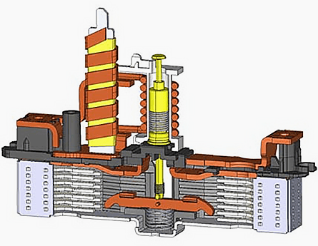
The contacts of a high current-limiting circuit breaker are forced open in the event of a short-circuit by a plunger and the current is directed immediately to the arcing chambers. The circuit is such broken even while the current is still rising.
The faster it breaks, the less energy has to be managed in the switch and the more compact the circuit breaker can be. This means that this is prerequisite for circuit breakers to be built with compact external dimensions.
Go back to Motor protection Elements ↑
3. Main contact system and switching capacity
The requirements on a motor circuit breaker main contacts are: a high making capacity, high breaking capacity, low heat dissipation at operational current, low contact erosion, small inertia and optimum shape for a favorable movement of the electric arc.
The switching arc should quickly be directed out from the area between the contact surfaces, cooled, divided, extended and thus extinguished. The de-ion plates must form a functional unit with the main contact with respect to shape and arrangement.
In order to optimally fulfill these high requirements, the very highest demands are placed on the design and materials and not least on the simulation and testing techniques.

Contact systems are designed to produce optimum switching performance at the main rated voltage. The number of de-ion plates is critical for the electric arc voltage during circuit breaking and hence for the switching capacity and current limitation.
For example a contact system designed for 400 V has a reduced switching capacity at supply voltages above 400 V (supply voltages below 400 V are thereby uncritical). Use at for example 690 V may therefore only be possible with reduced switching capacity. The performance data for the specified operational voltage should be respected.
Circuit breakers must be capable to control the largest possible short-circuit current at the point of installation at the given operational voltage.
If the switching capacity of the circuit breaker is smaller than required, then a backup protection must be provided (fuse or circuit breaker connected in series). The required switching capacity must be ensured in conjunction with the backup protection device. The sizing of the backup protection can be obtained from the product documentation.
Go back to Motor protection Elements ↑
3.1 Ultimate switching capacity and service switching capacity
IEC 60947-2 makes distinction between the rated ultimate short-circuit breaking capacity ICU and the rated service short-circuit breaking capacity ICS:
Rated ultimate short-circuit breaking capacity ICU
The test sequence is O-t-CO: Circuit breakers that have operated at the level of the ultimate short-circuit breaking capacity are only limited serviceable afterward. There may be changes in the overload tripping characteristic and increased temperature rises as a consequence of erosion of contact material.
Rated service short-circuit breaking capacity ICS
The test sequence is O-t-CO-t-CO: Circuit breakers that have operated at the level of the service short-circuit breaking capacity are further serviceable afterward.
Where:
- O – breaking the short-circuit from the closed state
- t – time interval
- CO – switching onto the short-circuit followed by breaking it
The ratings of circuit breakers for ICU are usually higher than for ICS. The majority of circuit breakers is therefore (for cost reasons) selected according to ICU. In plants in which down-time must be kept as short as possible, product selection should be based on ICS.
After a short-circuit has been broken, it is generally recommended to examine the device to make sure it is fully functional.
Go back to Motor protection Elements ↑
3.2 Let-through values
The essential quality attributes with respect to good short-circuit protection are the let-through values (see Figure 5 below). The magnitude of the cut-off current and let-through energy in relation to the prospective short-circuit current Icp provide information about the quality of current limitation by the switch.
They show the extent to which downstream devices such as contactors or switches are stressed in the event of a short-circuit.

The let-through values directly affect the sizing of these series-connected devices – for example short-circuit coordination type 2 without oversized contactors – and determine the constructional design of the installation.
Go back to Motor protection Elements ↑
3.3 Life span of circuit breakers
IEC 60947-2 defines the number of switching operations that a circuit breaker has to perform without load, at normal load, at overload or with a short-circuit. The values vary between two breaks (O-t-CO) for the rated ultimate short-circuit breaking capacity and a couple of thousand operations for purely mechanical switching without load.
The electrical life span (contact life span) of a circuit breaker like with contactors depends on the size of the current to be broken. Small currents in the order of the rated current or the tripping range of thermally delayed overload releases have a much smaller effect on the contact life than short-circuit currents of the magnitude of the breaking capacity (see Figure 6).
The contacts may be so eroded even after exposure to just a few high short-circuit currents that replacement of the circuit breaker is required.
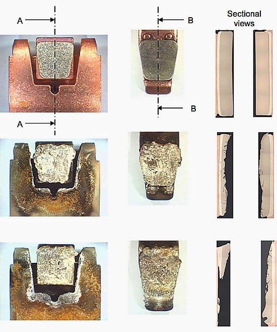
Where //
- Figures above: Contacts in new state.
- Figures in center: Contacts after approx. 75% of the electrical life span, contact material partially eroded and contacts still operable.
- Figures below: Contacts at the end of their life span, substrate material visible, contact material eroded down to the substrate. Further use would lead to contact welding and excessive temperature rise.
The short-circuit currents that arise in practice are usually well below the calculated maximum values and the switching capacity of the switches deployed. They therefore cause less contact erosion.
Go back to Motor protection Elements ↑
3.4 Operational switching
In the lower power range, circuit breakers are also used to manually operate smaller – frequently mobile – equipment and devices (for example milling machines, circular saws, submersible pumps). The electrical life of the switches is rarely used to the full at the low number of operations typical in these applications.
Go back to Motor protection Elements ↑
3.5 Auxiliary contacts and displays
Auxiliary contacts enable the functional integration of the protective device in the control system. ON, OFF, overload and/or short-circuit tripping can be signaled with the aid of the appropriate auxiliary contacts (see Figure 7). These auxiliary switches can be mounted on or inserted in the circuit breaker and are either connected to terminals or connectable via loose wire ends.

In addition to auxiliary switches, circuit breakers are often equipped with visual indicators of the state of operation and also often for the tripped state and the cause of tripping. These are valuable aids for diagnosis on site during commissioning and fault rectification.
Go back to Motor protection Elements ↑
3.6 Shunt-trip and undervoltage releases
Shunt-trip releases enable remote circuit breaking by means of a control signal, for example for electrical interlocking (Figure 8). The undervoltage release switches the circuit breaker OFF when the voltage falls below a (usually fix) certain level of the applied voltage and is used for example for detecting voltage outages.
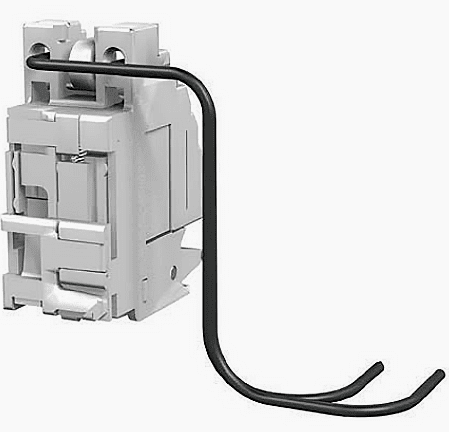
They are in particular used as safety components, for example to prevent automatic restarts after a voltage outage, for interlocking circuits, for EMERGENCY STOP functions and for remote release.
Go back to Motor protection Elements ↑
3.7 Motor (remote) operators
Motor or remote operator units (Figure 9) open the possibility to issue all commands to circuit breakers remotely. The functions that are usually manually performed can thus be actuated from remote. The load feeders can thus be switched-on and -off without direct intervention of an operator on site.
Resetting of a circuit breaker that has tripped is thus possible in remote-controlled distribution stations.
Go back to Motor protection Elements ↑
E300 Electronic Overload Relay (VIDEO)
Demonstration on how to wire/connect an E300 electronic overload relay to a 100-C Contactor and 140-U Motor protection Circuit Breaker.
Reference // Low-Voltage Switchgear and Controlgear – Technical Document by Allen Bradley
Related electrical guides & articles


Edvard Csanyi
Hi, I'm an electrical engineer, programmer and founder of EEP - Electrical Engineering Portal. I worked twelve years at Schneider Electric in the position of technical support for low- and medium-voltage projects and the design of busbar trunking systems.I'm highly specialized in the design of LV/MV switchgear and low-voltage, high-power busbar trunking (<6300A) in substations, commercial buildings and industry facilities. I'm also a professional in AutoCAD programming.
Profile: Edvard Csanyi

Please send me any design of the circuit.
IS IT ADVISABLE TO CHANGE THE MPCB AFTER 12 YEARS OF OPERATION?
Hi EEP team, Thanks for your wonderful article. But i have a doubt. In your article, you have mentioned differential release, do really MPCB have differential tripping?
Good article on Motor protection CB…one thing which was not mentioned is the utilization of magnetic blow out coils which are cleverly inserted in the current path. The resultant magnetic field helps to blow away the arc, lengthen it and cool it, which is crucial for arc extinction. During my post univ days at Siemens India, I was working on developing a new MCB design, and I had to study all MCBs in the market. One of them had a short ckt capacity of 25kA (unheard of in those days…early 90s). When I opened up the MCB, lo and behold there was a carefully designed blow out coil, which was responsible for the high kA rating.
Does this include US ANSI/NEMA ratings for the breakers ?
Shreesh…This article is aimed at attacking the basic concepts of motor circuit protection and device details. If you are looking for specific ratings (possibly for US LV systems at 480V), you need to visit Eaton’ Application Guide or Square D which will have all the requisite ratings. Another good reference is NEMA ICS 2. If you need speific question on ratings, let us know.
Good analysis about motor protection,..i have a doubt.I want to know about mpcb tripping time delay,. Suppose mpcb setting is 10A, & it will take 11A , then after how much second it will trip.