
The Mesh Current Method //
The mesh current method of circuit analysis discussed in this technical article employs mesh currents as the independent variables. The idea is to write the appropriate number of independent equations, using mesh currents as the independent variables. Subsequent application of Kirchhoff’s Voltage Law (KVL) around each mesh provides the desired system of equations.
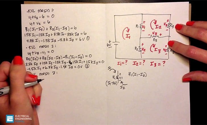 The Mesh Current Method For Analysis Of Electric Circuits (photo credit: Michelle Munteanu via Youtube)
Figure 1: The current i, defined as flowing from left to right, establishes the polarity of the voltage across R.
In the mesh current method, we observe that a current flowing through a resistor in a specified direction defines the polarity of the voltage across the resistor, as illustrated in Figure 1, and that the sum of the voltages around a closed circuit must equal zero, by KVL. Once a convention is established regarding the direction of current flow around a mesh, simple application of KVL provides the desired equation. Figure 2 illustrates this point.

Figure 2: Once the direction of current flow has been selected, KVL requires that:
v1 – v2 – v3 = 0.
The number of equations one obtains by this technique is equal to the number of meshes in the circuit. All branch currents and voltages may subsequently be obtained from the mesh currents, as will presently be shown. Since meshes are easily identified in a circuit, this method provides a very efficient and systematic procedure for the analysis of electric circuits.
The following box outlines the procedure used in applying the mesh current method to a linear circuit.
In mesh analysis, it is important to be consistent in choosing the direction of current flow. To avoid confusion in writing the circuit equations, unknown mesh currents are defined exclusively clockwise when we are using this method. To illustrate the mesh current method, consider the simple two-mesh circuit shown in Figure 3.

circuit
This circuit is used to generate two equations in the two unknowns, the mesh currents i1 and i2. It is instructive to first consider each mesh by itself. Beginning with mesh 1, note that the voltages around the mesh have been assigned in Figure 4 according to the direction of the mesh current i1.
Recall that as long as signs are assigned consistently, an arbitrary direction may be assumed for any current in a circuit. If the resulting numerical answer for the current is negative, then the chosen reference direction is opposite to the direction of actual current flow.
Thus, one need not be concerned about the actual direction of current flow in mesh analysis, once the directions of the mesh currents have been assigned. The correct solution will result, eventually.

Figure 4: Mesh 1 – KVL requires that: vS – v1 – v2 = 0
where:
- v1 = i1R1,
- v2 = (i1 – i2)R2.
According to the sign convention, then, the voltages v1 and v2 are defined as shown in Figure 4 (see above).
Now, it is important to observe that while mesh current i1 is equal to the current flowing through resistor R1 (and is therefore also the branch current through R1), it is not equal to the current through R2.
The branch current through R2 is the difference between the two mesh currents i1 − i2. Thus, since the polarity of voltage v2 has already been assigned, according to the convention discussed in the previous paragraph, it follows that the voltage v2 is given by:
v2 = (i1 − i2)R2 – equation 1
Finally, the complete expression for mesh 1 is:
vS − i1R1 − (i1 − i2)R2 = 0 – equation 2
The same line of reasoning applies to the second mesh. Figure 5 (see below) depicts the voltage assignment around the second mesh, following the clockwise direction of mesh current i2. The mesh current i2 is also the branch current through resistors R3 and R4.

Figure 5: Mesh 2 – KVL requires that v2 + v3 + v4 = 0 where:
- v2 = (i2 – i1)R2
- v3 = i2R3
- v4 = i2R4
However, the current through the resistor that is shared by the two meshes, denoted by R2, is now equal to i2 − i1; the voltage across this resistor is:
v2 = (i2 − i1)R2 – equation 3
and the complete expression for mesh 2 is:
(i2 − i1)R2 + i2R3 + i2R4 = 0 – equation 4
The reason for this apparent discrepancy is that the voltage assignment for each mesh was dictated by the (clockwise) mesh current. Thus, since the mesh currents flow through R2 in opposing directions, the voltage assignments for v2 in the two meshes are also opposite. This is perhaps a potential source of confusion in applying the mesh current method.
You should be very careful to carry out the assignment of the voltages around each mesh separately.
Combining the equations for the two meshes, we obtain the following system of equations:
(R1 + R2)i1 − R2i2 = vS − R2i1 +(R2 + R3 + R4)i2 = 0 – equation 6
These equations may be solved simultaneously to obtain the desired solution, namely, the mesh currents i1 and i2. You should verify that knowledge of the mesh currents permits determination of all the other voltages and currents in the circuit.
Mesh-Current Method for Circuit Analysis (VIDEO)
The technique Michelle Munteanu is demonstrating here is a simplified version of Mesh Current Method that was relevant to the type of circuits we were analyzing in the class.
Reference // Fundamentals of electrical engineering by Giorgio Rizzoni (Get it from Amazon)


I’m designing a program to analyse large-scale electrical circuit transients involving linear/nonlinear R, L & C elements and (ideal) switches. First challenge is forming the meshes. I want to select the meshes so that nonlinear & switched branches are in the co-tree: so preserving/maximising sparsity and ensuring independent meshes.
Any ideas on suitable tree-forming algorithms? Most mesh analysis texts assume you can choose the meshes “by eye” or “just write them down”.
Seems to me there are two choices: (i) select the tree branches according their ‘type’ so that inductive/nonlinear/switched branches are in the co-tree; (ii) form the tree ignoring branch type(?) then sequentially swap tree and co-tree branches to the same end. But how to aim for sparsity?
All suggestions welcomed, and maybe even acknowledged.
I remembered old times at the university
Excellent for students and professionals