High speed protection scheme
The separation of equipment into zones will only work successfully if the outputs of the protections can be guaranteed to do their job. This makes logical sense.
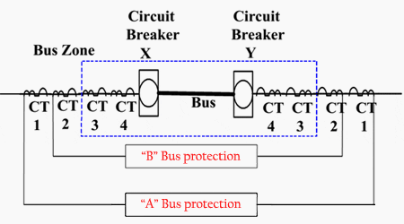
For the bus protection in Figure 1 for example, the breakers X and Y must trip on a fault, otherwise the adjacent zone providing power to the fault must be tripped.
Similarly, for breaker X in Figure 2, the adjacent zone H2 would have to be tripped if breaker X did not open. However, to maintain the speed and security in protection zones the use of timed backup protections is minimized.
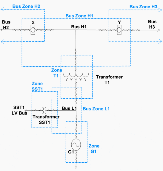
The addition of a timed backup decreases the speed and also the larger backup zone reduces security. The solution is to add a separate protection on the breaker itself, to guarantee that it will either open correctly or removed adjacent elements from service.
If, for example in Figure 3, breaker X fails to clear a fault, all of the equipment on bus H2 as well as bus H1 would be given a trip signal via the breaker failure protection scheme.
A breaker will be considered to have failed if, after the trip signal has been generated, the breaker has:
- Not started opening within a preset time frame (determined by switches internal to the breaker),
- The breaker has not fully opened within a preset time frame (determined by switches internal to the breaker), or
- If the current has not been broken by the breaker within a preset time (determined by current measurement devices).
Breaker failure protections are used on breakers at any voltage level, but are predominant on 13.8kV systems and above. The more impact a failed breaker will have on electrical system stability, the more necessary to use this high speed breaker failure protection.
Lower voltage levels 13.8kV and below may use timed backup protections if the fault clearing time is not crucial.
Duplicate A and B Protections
Invariably each one of discrete high-speed protection zones utilize two high-speed duplicate protections. They are often called A and B, but could be named anything (i.e., C&D, R&S, Even & Odd, etc.). The alternative to using duplicate protections would be the use of a main high-speed protection and a timed backup.
They will have the following 6 common features:
1. Functionally identical
The duplicate protections both fulfil the same purpose and either one could be removed from service without affecting the protection of the equipment.
2. Not physically identical
They use different types of protection design or different relay types. Ifone of the protections were to fail due to a system problem (i.e., harmonics in the current waveform), there would be less chance of the other protection failing also.
3. Separate Battery Supplies //
To maintain redundancy, separate battery supplies must be provided for each protection.
4. Separate routing of wiring/
Equipment and wiring are physically separated to reduce possibilities of common faults.
5. Separate Inputs
The protections utilize signals from completely separate current and voltage transformers. Other equipment data that is input tothe protections (i.e., pallet positions, temperature sensors, mechanical interlocks, etc.) are also duplicated.
6. Separate Outputs
The protections have separate output signals to the circuit breakersor other electrical devices. Quite often the devices will have duplicate trip coils installed to facilitate complete separation.
Figure 3 below illustrates the philosophy of duplicate (A and B) protections.
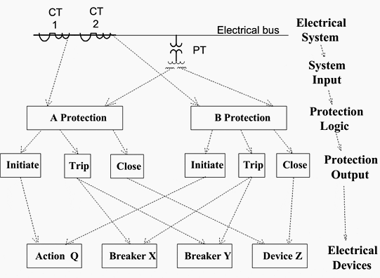
Reference // Science and Reactor Fundamentals – Electrical CNSC Technical Training Group




Mozambique Maputo, continent of Africa…Since I have signed in its daily lessons from EEP, I am improving my skills in different parts of energy sector….I really appreciate for doing this for me
With respect to Mr Csanyi’s efforts I would like to see a more extensive discussion on the matter of breaker failure and backed-up protection schemes, detailing the philosophy and implementation of bus zone protection. Reference to the problem of battery failure in a substation would be welcome.
I found the article misleading. While it does refer to breaker failures it does not explain why the adjacent breakers must open. In my mind it is not the adjacent breaker which must open but the preceding breaker in the supply scheme.
I agree that this article is about duplicate protection. Breaker protection is inherent in cascading but may be enhanced by introducing further devices to clear the fault by initiating a response from the next breaker in line, before cascading takes place in response to a breaker failure. The case of substation battery failures are particularly worrying as a cascaded system is not likely to respond soon enough to clear the fault at the higher primary voltage..
i think many are assuming that the article is supposed to be about how breaker fails, and what should be done about it. In my humble opinion, the article is about redundancy in protection – How a well-designed system prevents damage when a circuit breaker fails – for any one of several reason, In that sense, the article covers the subject very well….as is usual from Edvard,
Breaker Failure protection is not elaborately explained here. Duplicate protection is a different topic to that of Breaker Failure Protection. Drawings are explaining Duplicate Protection not the Breaker Failure Protection.