
Estimated Study Time: 6 minutes
Possibly 40 times the full-load current
When a transformer is first energized or reenergized after a short interruption, the transformer may draw inrush current from the system due to the core magnetization being out of sync with the voltage. The inrush current may approach short-circuit levels, as much as 40 times the transformer’s full-load current.
 Beware Of Transformer Inrush Current (photo credit: transformers-magazine.com)
Inrush current may cause fuses, reclosers, or relays to falsely operate. It may also falsely operate faulted-circuit indicators or cause sectionalizers to misoperate.
Attempted interruption anywhere here leaves Br on the core.
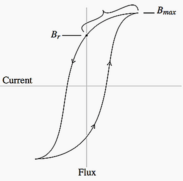
The worst inrush occurs with residual flux left on the transformer core.
Consider Figure 1 and Figure 2, which shows the worst-case scenario. A transformer is deenergized near the peak core flux density (Bmax), when the voltage is near zero.
The flux decays to about 70% of the maximum and holds there (the residual flux, Br). Some time later, the transformer is reenergized at a point in time when the flux would have been at its negative peak. The system voltage is crossing through zero and rising positively.

The positive voltage creates positive flux that adds to the residual flux already on the transformer core (remember, flux is the time integral of the voltage!).
This quickly saturates the core. The effective magnetizing branch drops to the air-core impedance of the transformer.
The air core impedance is roughly the same magnitude as the transformer’s leakage impedance. Flux controls the effective impedance, so when the transformer core saturates, the small impedance pulls high-magnitude current from the system. The core saturates in one direction, so the transformer draws pulses of inrush every other half cycle with a heavy dc component. The DC offset introduced by the switching decays away relatively quickly.
Figure 3 shows an example of inrush current following a reclose operation measured at the distribution substation breaker.

4 factors significantly impact inrush current //
1. Closing point
The point where the circuit closes back in determines how close the core flux can get to its theoretical maximum. The worst case is when the flux is near its peak. Fortunately, this is also when the voltage is near zero, and switches tend to engage closer to a voltage peak (an arc tends to jump the gap).
2. Design flux
A transformer that is designed to operate lower on the saturation curve draws less inrush current. Because there is more margin between the saturation point and the normal operating region, the extra flux during switching is less likely to push the core into saturation.
3. Transformer size
Larger transformers draw more inrush, that’s the fact. Their saturated impedances are smaller. But, on a per-unit basis relative to their full-load capability, smaller transformers draw more inrush. The inrush into smaller transformers dies out more quickly.
4. Source impedance
Higher source impedance relative to the transformer size limits the current that the transformer can pull from the system. The peak inrush current with significant source impedance (Westinghouse Electric Corporation, 1950) is defined as:

where //
- i0 – peak inrush current without source impedance in per unit of the transformer rated current
- X – source impedance in per unit on the transformer kVA base
Other factors have less significance. The load on the transformer does not significantly change the inrush. For most typical loading conditions, the current into the transformer will interrupt at points that still leave about 70% of the peak flux on the core.
While interruptions generally cause the most severe inrush, other voltage disturbances may cause inrush into a transformer. Voltage transients and especially voltage with a DC component can saturate the transformer and cause inrush.
Some examples are:
Voltage sags – Upon recovery from a voltage sag from a nearby fault, the sudden rise in voltage can drive a transformer into saturation.
Sympathetic inrush – Energizing a transformer can cause a nearby transformer to also draw inrush. The inrush into the switched transformer has a significant dc component that causes a dc voltage drop. The DC voltage can push the other transformer into saturation and draw inrush.
Lightning – A flash to the line near the transformer can push the transformer into saturation.
Reference // Electric power distribution equipment and systems / T.A. Short (Purchase at Amazon)
Related electrical guides & articles


Edvard Csanyi
Hi, I'm an electrical engineer, programmer and founder of EEP - Electrical Engineering Portal. I worked twelve years at Schneider Electric in the position of technical support for low- and medium-voltage projects and the design of busbar trunking systems.I'm highly specialized in the design of LV/MV switchgear and low-voltage, high-power busbar trunking (<6300A) in substations, commercial buildings and industry facilities. I'm also a professional in AutoCAD programming.
Profile: Edvard Csanyi

Edvard,
I would like some help.
I need to power five transformers in parallel of 1 MVA each 13.8 kV – delta. How do I calculate the total inrush current to avoid instantaneous element tripping?
What factor should be multiplied by In?
Hi Edison,
We can help you with your problem.
If you are energizing all of them simultaneously, you can estimate the current by taking the nominal current of one of them and multiply it by 50 (5 transformers, 10x inrush current).
If you have more data available we can help you with a simulation.
Please notice, that if the system is large enough you shouldn’t have a problem. for example. 5MVA in a 375MVA system, shouldn’t cause a voltage drop larger than 5%. It is only a problem if the system is weak.
At Southern States, we offer a product called Transwitcher especifically designed for this application. Please feel free to contact me is you have any questions.
Use CSDs(Controlled Switching Devices)
Thanks Edvard.Very Interesting
Thanks for these informative materials on electrical engineering!
Phenomena of Ferroresonance is also there which contributes to inrush current and tripping of protective devices. Kindly explain that too, in easy words.
Okay, we now know what causes it.
How do we avoid it?
What can we do to avoid it while bringing a transformer back on line, especially if other transformers in system are close by? Also what to do depending on the various circumstances that may cause it.
To accommodate high inrush current, you can use fuses which have time-current withstand values of at least 12 times transformer primary rated current for 0.1 second and 25 times for 0.01 second.