
Estimated Study Time: 7 minutes
Low voltage switchgear
Low voltage switchgear and distribution boards form the link between the equipment for the generation (generators), transmission (cables, overhead lines) and transformation (transformers) of electrical energy on the one hand and the consumers, e.g. motors, solenoid valves, devices for heating, lighting, air conditioning, and the information technology on the other hand.
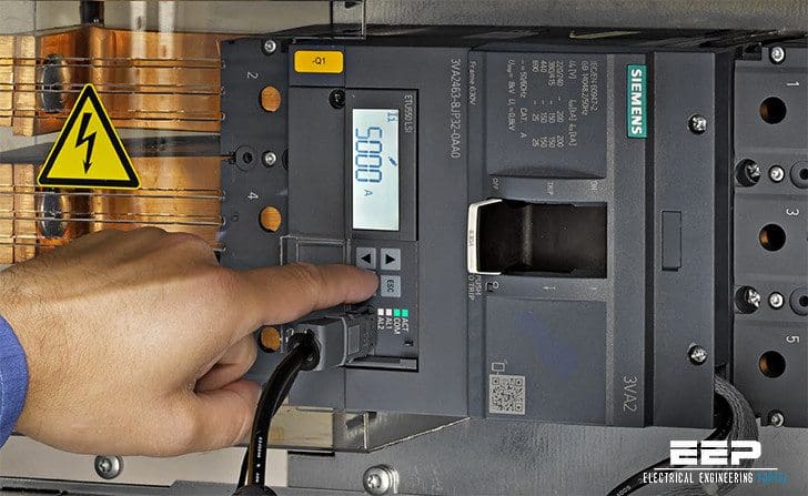 6 things you MUST know when designing low voltage switchgear (photo credit: SIEMENS)
For alternating voltage, the rated voltage is 1,000 V max., for direct voltage it is 1,500 V max.
NOTE // In the IEC/VDE standards, the term “power switchgear and controlgear, PSC assembly” is used.
Like medium voltage switchgear, low voltage switchgear is also less often installed with individual panel design on site, but delivered as factory assembled, type-tested switchgear. For design verification, testing is to be accomplished successfully in compliance with IEC 61439-1 (VDE 0660-600-1) and IEC 61439-2 (VDE 0660-600-2).
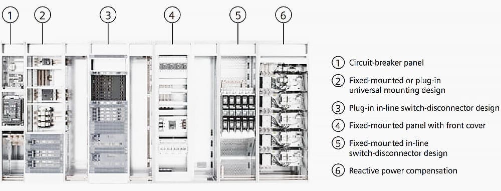
Generally, the mounting designs for switchgear equipment can be selected dependent on the usage. Switchgear design usually involve some of these //
- Circuit-breaker design
- Universal mounting design
- In-line switch-disconnector design
- Fixed-mounted design
- Reactive power compensation
Test verification under arcing fault conditions in accordance with IEC / TR 61641 (VDE 0660-500, Addendum 2) ensures maximum safety of persons. Protective measures such as high-quality insulation of live parts (for example busbars), uniform and easy handling, integrated operator fault protection, and reliable switchgear dimensioning prevent arcing faults and hence personal injuries.
The essential selection criteria according to which low voltage switchgear and distribution boards are designed are the following //
Rated currents
- Rated current Ir of the busbars
- Rated current Ir of the feed-in
- Rated current Ir of the branch circuits
- Rated short-time current Icw of the busbars
- Rated peak short circuit current Ipk of the busbars
Degree of protection and type of installation
- Degree of protection in accordance with IEC 60529 (VDE 470-1)
- Protection against electric shock (safety class) inaccordance with standard IEC 60364-4-41 (DIN VDE 0100-410)
- Enclosure material
- Type of installation (on the wall, stand-alone)
- Number of front operating panels
Type of device installation
- Fixed installation
- Plug-in design
- Withdrawable unit design
- Snap-on fixing on mounting rail
Usage
- Main switchgear or main distribution board
- Sub-distribution board
- Line distribution board
- Motor, installation, industry distributor
- Light or power distributor
- Reactive power compensation unit
- Control unit
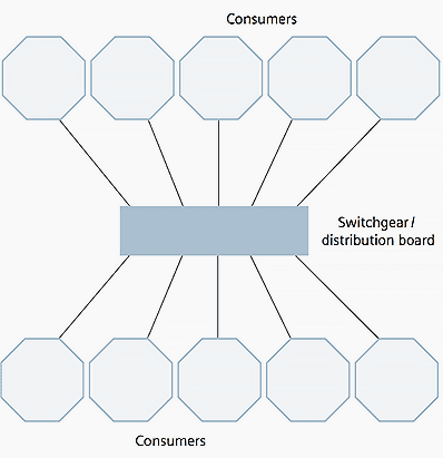
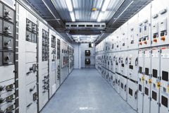
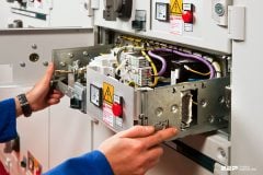
Depending on the type of power distribution, a differentiation is made between point-to-point distribution boards and line distribution boards. In point-to-point distribution boards, the electric power is distributed radially from a spatially limited system (see Figure 1).
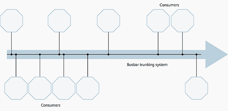
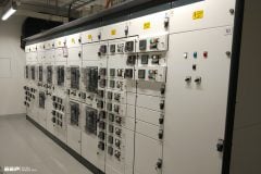
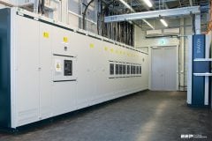
Whereas in line distribution boards – today mostly busbar trunking systems – the individual power tappings take place via spatially separated equipment and the power is transmitted to these tap-off units by means of encapsulated busbars (see Figure 2).
In point-to-point distribution boards, one transformer per busbar section supplies the main switchgear. The downstream motor distributors, control units, distributors for lighting, heating, air conditioning, workshops, etc. – that is, those fed by the main switchgear in turn – are referred to as sub-distribution boards.
The combination of a main switchgear with feed-in transformer is referred to as transformer load centre substation.
Due to its compactness it provides a secure and economic option of distributed power supply in compliance with the factory-assembled stations described in IEC 62271-202 (VDE 0671-202).
When planning low voltage switchgear, the prerequisite for efficient dimensioning is the knowledge of the local conditions, the switching duty, and the demands on availability.
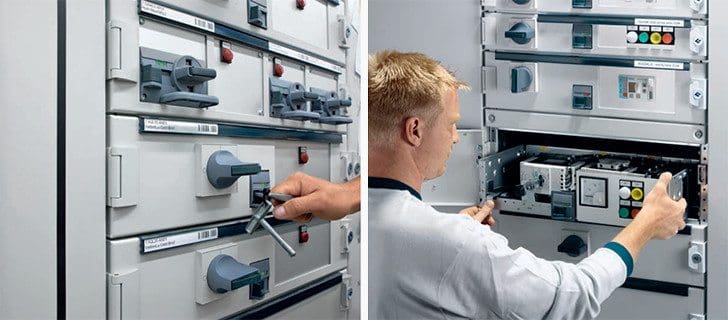
In a power distribution system or motor control centre for a production plant, however, replaceability and reliability of supply are the most important criteria in order to keep downtimes as short as possible.
A vital basis here is deploying withdrawable unit systems both in circuit breaker protected and in fuse protected design.
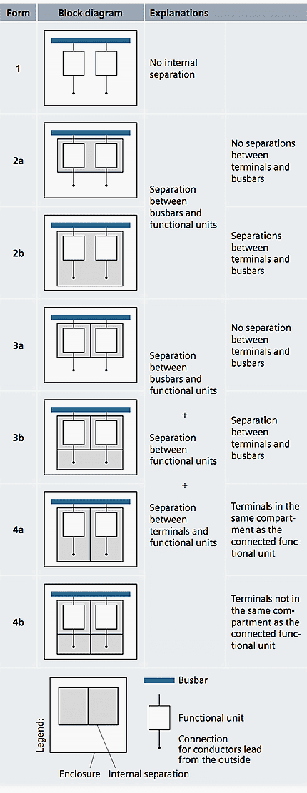
Forms of internal separation
A multi-purpose low voltage switchgear installation is characterized by numerous combination possibilities of different mounting designs within one panel and variable forms of internal separation. The forms described in IEC 61439-2 (VDE 0660-600-2) are listed in Table below.
Siemens SIVACON S8 General Plant Design
Reference // Totally Integrated Power – Low Voltage Switchgear and Distribution Systems by SIEMENS
Related electrical guides & articles


Edvard Csanyi
Hi, I'm an electrical engineer, programmer and founder of EEP - Electrical Engineering Portal. I worked twelve years at Schneider Electric in the position of technical support for low- and medium-voltage projects and the design of busbar trunking systems.I'm highly specialized in the design of LV/MV switchgear and low-voltage, high-power busbar trunking (<6300A) in substations, commercial buildings and industry facilities. I'm also a professional in AutoCAD programming.
Profile: Edvard Csanyi

Dear Edvard,
Could you assist me in explaning the difference between TN-S & TT System in term of:
(1) application in building construction
(2) Wiring diagram
(3) Advantage & Disadvantage
(4) Why TN-S and not TT
(5) Why TT and not TN-S
(6) Singapore only adopt these 2 Earthing System
Dear Sir,
Thank your for explanation of the Reactive Power problems.
Im instructed some of enloge of electrical