Generators, motors, transformers & lines
The three basic principles of differential protection explained in this article, which has been known for decades, are still applicable and independent of the specific device technology. The differential protection compares the measured values with regard to magnitude and phase. This is possible by direct comparison of instantaneous values or by vector (phasor) comparison.

In each case, the measurement is based on Kirchhoff’s laws which state that the geometric (vector) sum of the currents entering or leaving a node must add up to 0 at any point in time.
The convention used in this context states that the currents flowing into the protected zone are positive, while the currents leaving the protected zone are negative.
Generators, motors, and transformers are often protected by differential protection, as the high sensitivity and fast operation are ideally suited to minimize damage. On feeders, differential protection is mainly used to protect cables, particularly on short distances where distance protection cannot be readily applied.
- Current differential protection
- Biased (stabilized) differential protection
- Differential Protection with two pilot wire cores
1. Current differential protection
This is the simplest and most frequently applied form of differential protection. The measuring principle is shown in Figure 1. The current transformers at the extremities of the differential protection zone are connected in series on the secondary side so that the currents circulate through the current transformers during an external fault (see Figure 1a) and no current flows through the differential measuring branch where the differential relay is situated.
In the event of an internal fault (Figure 1b) the fault currents flow towards the fault location so that the secondary currents add up and flow via the differential branch. The differential relay picks up and initiates tripping.
Figure 1 – Measuring principle: External fault or load (a), Internal fault (b)


This simple circuit principle (non-biased current differential protection) may be used on all non-distributed protection objects where the current transformers are located in close physical proximity to each other.
The simplest arrangement results with generators or motors (Figure 2a), in particular when the current transformers have the same ratio. The transformer protection requires interposing current transformers for the vector group and ratio correction of the currents used for the comparison (Figure 2b).
Figure 2 – Differential protection, the three-phase basic principle


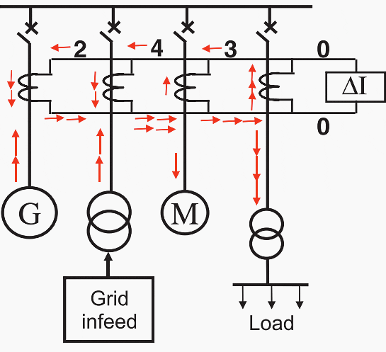
For busbar protection, the currents from a number of feeders must be summated (Figure 3). In the case of load and external faults, the vector sum of the feeder currents is equal to zero, so that no differential current flows in the relay.
During internal faults, the currents however add up to a large differential current.
Figure 3 – Busbar protection (load or through fault condition)

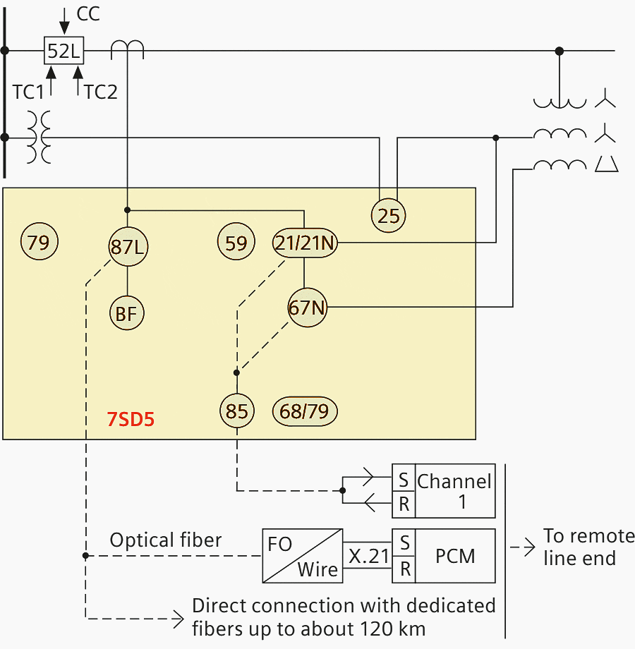
For feeder differential protection, the current transformers at the two terminals of the protected object are far apart. In this case, the connection circuit according to Figure 4 is used (three core pilot differential protection). Three pilot wire cores are required for the connection between the two stations, which typically are provided as a “twisted triplet” via a communication cable.
In practice, the current transformer secondary currents (1 or 5 A) are converted to 100 mA by interposing current transformers to reduce the burden of the pilot wire cores. The current differential protection may be used over distances of approximately 10 km due to this reduced current transformer burden.
Over short distances of 1 to 2 km, control cables (2 kV isolation) may be used.
Figure 4 – Line differential protection


When the pilot wire cables are in close proximity to power cables or overhead lines, adequate screening against fault currents via earth is required. On longer distances, high voltages of several kV may be induced in the pilot wires. This affects the isolation of the pilot wires against the earth, and requires special pilot wire cables with higher insulation (e.g. 8 kV), and may necessitate barrier transformers to prevent the high voltages from reaching the protection relays.
To further reduce the number of pilot wire cores required, the interposing current transformers are also summation transformers, whereby the phase currents are combined to a single (summated) composite current.
1.1 Current comparison with digital measured value transmission
The principle of current differential protection was so far described, based on the classic mode of 50/60 Hz analog measured value transmission via pilot wire communication. With numerical protection, the application of serial data transfer is increasingly used.
The comparison protection circuits described above are also designated as “longitudinal differential protection”. For the sake of completeness the transverse differential protection that was used previously, must also be mentioned. It compared the current at the terminals of two or more circuits connected in parallel.
This type of protection is hardly ever used anymore with lines in particular because the circuits must be connected in parallel for this type of protection and may not be operated independently.

Only with generators that have parallel (split) windings in each phase brought out to separate terminals, the transverse differential protection is still used against turn faults.
2. Biased (stabilized) differential protection
So far, for the sake of simplicity, a fixed pick-up threshold was assumed for the relay measuring the current in the differential circuit. In practice, however, a false differential current resulting from transformation errors of the current transformers must be considered. In the linear range of the current transformers, this error is proportional to the through current.
In the event of large fault currents, CT saturation may be the result, causing a rapid increase of this false differential current. Additionally, transformer tap changers will cause a false current due to the modification of the transformation ratio.
Figure 6 shows the differential current measured by the relay, related to the through current (Ithrough) during load or external faults.
Figure 6 – False differential current during load and external faults with adapted relay characteristic
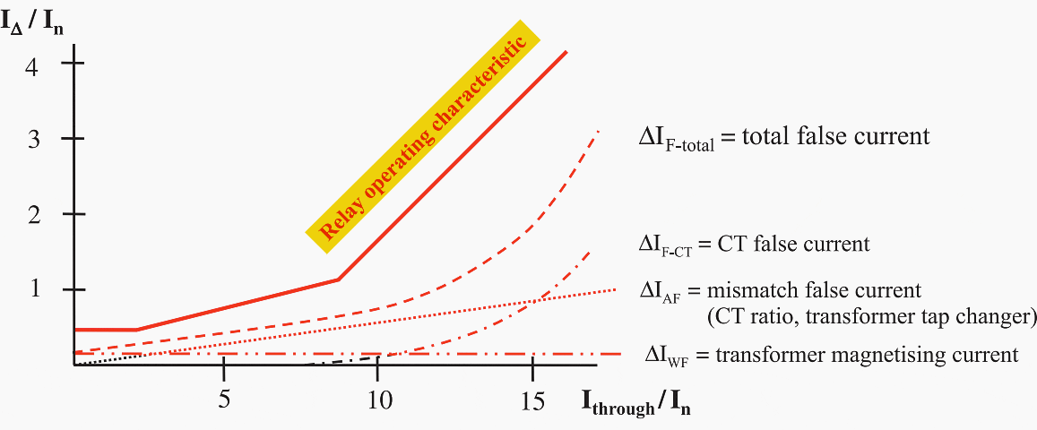

It is apparent that the pick-up threshold should be increased when the through current increases. This results in high sensitivity during load and small fault currents, while at the same time providing improved stability against mal-operation with large currents when CT saturation is expected.
In the early days of protection, this was achieved by increasing the pick-up threshold proportionally to the through current. This method was already suggested in 1920 as a biased differential relay. The principle of operation is shown in Figure 7 – Biased differential relay according to McCroll.
Figure 7 – Biased differential relay according to McCroll


Electromechanical and static relays implemented this method using a rectifier bridge comparator Figure 7. The measuring path was implemented with a polarised moving coil relay having high sensitivity and later with an electronic trigger circuit. Bias (stabilization) was provided by the signal IBias = k1 × (I1 − I2) which corresponds to the “sum” of the CT currents in the event of a through current.
In this regard, the chosen sign convention for the currents must be observed; it designates the currents as positive when they flow into the protected object. Operation is affected by the “difference” of the CT currents IOp = k2 × (I1 + I2).
The following states result:
Table 1 – Bias (stabilization) and the difference” of the CT currents
| IBias = k1 × (I1 − I2) | IOp = k2 × (I1 + I2) | |
| External fault | IBias = 2 × k1 × IF | IOp = 0 |
| Internal fault with single end in-feed | IBias = k1 × IF | IOp = k2 × IF |
| Internal fault with in-feed from both ends | IBias = 0 | IOp = 2 × k2 × IF |
The pick-up criterion is: IOp > IBias
ie. k2 × |I1 + I2| > k1 × |I1 – I2|
By means of a restraint spring on the pick-up relay, a minimum pick-up threshold B can also be applied. The principle equation for the biased differential protection is thus obtained:
|I1 + I2| > k1 × |I1 – I2| + B whereby k = k1/k2
This allows better adaptation to the area of false current measurement that must be excluded.
Figure 8 – Differential protection with bridge rectifying circuit in the measuring path
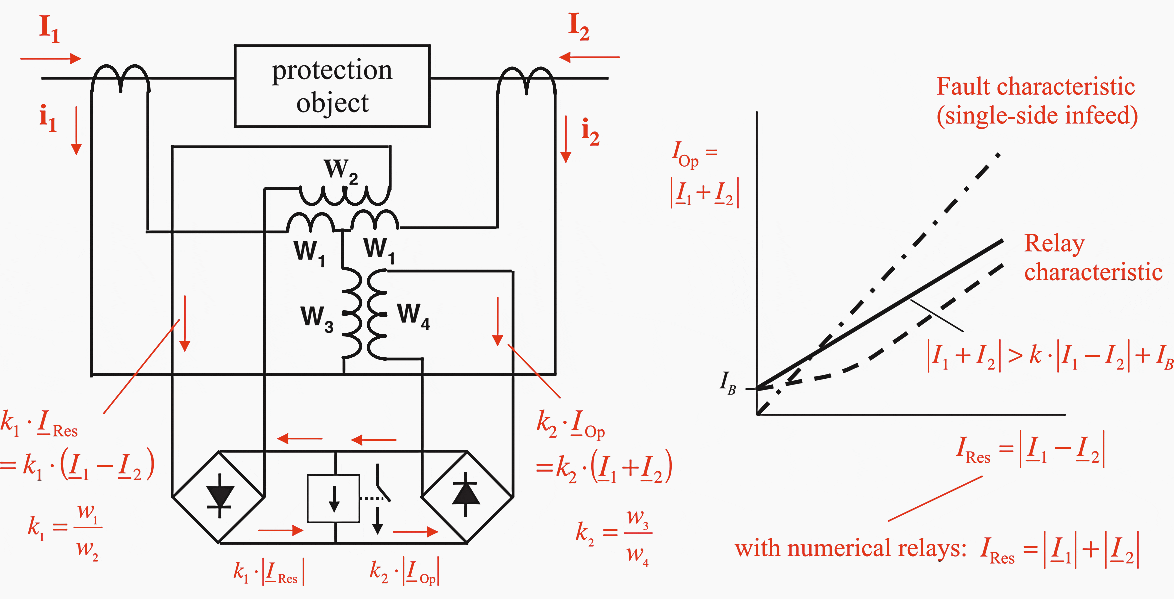

In newer protection devices, the threshold B is no longer added to the restraining side but is provided as a separate setting value: IOp > B. As a result, the biased characteristic IOp > k×IRes is no longer displaced by the initial value B but instead passes through the origin of the coordinates.
Consequently, increased sensitivity with small currents is achieved.
The described measuring principle may also be applied to protection objects having more than two terminals (three winding transformers or busbar protection). Thereby the sum of the current magnitudes (arithmetic sum) is used for the restraint1 while the magnitude of the geometric (vectorial) sum of the currents is used for operation:
- IRes = |I1| + |I2| + |I3| + … + |In|
- IOp = |I1 + I2 + I3 + … + In|
The conditions stated above apply as pick-up criterion: IOp > k×IRes and IOp > B
This is referred to at length in the section regarding the individual protection systems. The corresponding circuit based on analog signal processing is shown in Figure
9 below. The magnitude computation is achieved with the rectification.
In the event of an external fault, the operating current IOp must be zero, i.e. the current vectors must add up to zero. The restraint current corresponds to the sum of the current magnitudes.
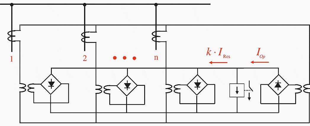

Where,
- IOp = |I1 + I2 + I3 + … + In| = |ΣI|
- IRes = |I1 + I2 + I3 + … + In| = |ΣI|
In the case of an internal fault, the operating current is the result of the summated current vectors. In its simplest form, when the in-feeds and consequently also the associated fault currents are all approximately in phase, the vector and the magnitude sums are equal i.e. IOp = IRes.
Under normal circumstances (low resistance fault and phase-equivalent in-feeds) the following may be noted:
Table 2 – External and internal faults
| External fault | IRes = 2 × IF-thru | IOp = 0 | IF-thru is the fault current flowing through the protected object |
| Internal fault | IRes = IF-int | IOp = IF-int | IF-int is the sum of the fault currents at the fault location |
In the event of internal faults with relatively large fault resistance, it must however be considered that part of the load current may still be flowing through the protected object during the fault. The through flowing load current is superimposed onto the fault currents flowing into the protected object.
The ratio IOp/IRes correspondingly reduces.
2.1 Example
Short circuit with fault resistance (Figure 10):
- IOp = 2300 – 300 = 2000
- IRes = 2300 + 300 = 2600
- IOp/IRes = 0.77
Figure 10 – lnternal fault with fault resistance, current distribution


In expansive transmission systems or in the event that power swings or even out of step conditions arise, the fault currents flowing into the fault location may however have substantial phase angle differences. In this case, the vectorial sum of the currents is smaller than the sum of the current magnitudes and therefore IOp < IRes.
For a two-ended in-feed, the conditions according to Figure 11 will result. If for the sake of simplicity, the two currents are assumed to have equal magnitude, then the following applies:
IRes = 2 × |IF| and IOp = 2 × cos (δ/2)
When δ = 30°, the lower ratio IOp/IRes = 0.87 results.
Figure 11 – Internal fault with a phase shift between in-feeds
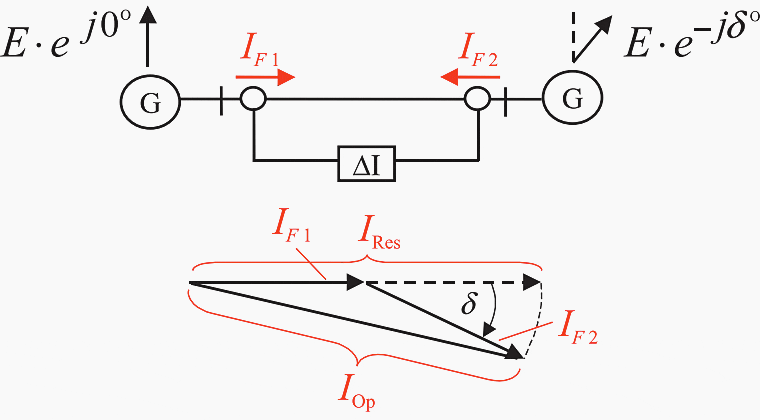

The observed effects may of course also be compounded. The bias (stabilization) factor k should therefore not be set above 0.8. On the contrary, the current transformers should be chosen such that a setting above 0.7 is not necessary.
2.2 Important notes
Note #1
In the protection literature and relay manuals, very often the flowing current is taken as reference and counted positive. In this case, the operating current corresponds to IOp = |I1 − I2| (differential current) and the restraint current IRes = |I1 + I2| with traditional relays or IRes = |I1 + I2| with numerical relays. This rule, which fits for the protection of two-terminal objects, however, is impractical in the case of multiple end protection objects like busbar protection.
Note #2
In this article, the restraint quantity corresponds to the sum of the current magnitudes IRes = (|I1 + I2|). The IOp/IRes locus for internal faults is in this case a straight line with 45° inclination (100% slope) in the operating/restraint diagram (see Figure 8). This also applies to all Siemens relays.
Some relay manufacturers only use one-half of the current sum as restraint quantity: IRes = (|I1 + I2|)/2 even with multi-terminal protection, i. e. IRes = (|I1|+ |I2|+ |I3| … + |In|)/2.
In this case, the internal fault locus has a 200% slope! This has to be kept in mind for comparing relays of different make and setting the bias factor (slope percentage).
3. Differential Protection with two pilot wire cores
The pilot wire differential protection (twisted-pair pilot wires) was developed for the application with communication cables having twisted pilot wire pairs (telephone cables). It is primarily used outside continental Europe, where the twisted pairs are often leased from telephone companies.
Two variants are in essence possible:
- Opposed voltage principle (tripping pilot scheme)
- Circulating current principle (blocking pilot scheme)
Both variants were developed and applied in practice. The relays manufactured by Siemens, operate with the opposed voltage principle.
3.1 Voltage comparison (opposed voltage principle)
With this technique, the current at each line terminal is routed through a shunt resistance (RQ) thereby producing voltages U1 and U2 each proportional to the corresponding current Figure 12. These two voltages are then compared via the pilot wire pair.
This current, which is only a few mA referred to the nominal current of the current transformers, results in tripping via the sensitive current relay (ΔI).
[highligt2]Figure 12[/highlight2] – Line differential protection, voltage comparison principle


The voltage on the pilot cores is only a few volts when nominal current flows via the CTs but rises in case of large fault currents. The maximum transverse voltage on the pilot cores may however not be greater than 60% of the rated insulation voltage of the telephone cable (500 V), in other words, 300 V.
To restrict the voltage in the event of heavy internal fault currents, a varistor is provided.
In addition, the pilot wire cores must be properly twisted so that the transverse voltage induced by the fault current in the earth, which influences the measurement, is reduced to a minimum.
The measuring circuit applied in practice operates with the biased differential protection principle. The operating current 1 is thereby proportional to the pilot wire current. The biasing current is obtained from the current in the shunt branch together with a supplementary component from the pilot wire current (Figure 13).
Figure 13 – Two core pilot wire differential protection – opposed voltage principle
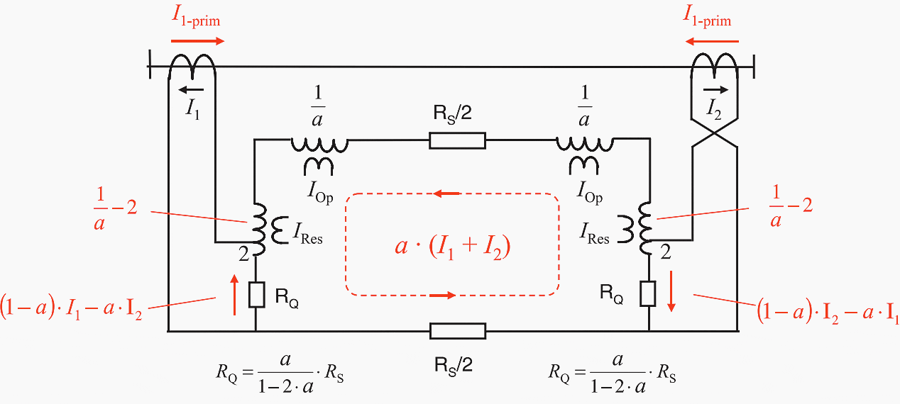

To obtain IOp and IRes, the pilot wire and shunt currents are summated in the relay with the indicated weighting factors. In analog devices, this is done by internal interposing transformers with corresponding tappings. See Figure 13.
RQ = k × RS / (1 – 2 × k)
The analog relays manufactured by Siemens always implement a fixed value k = 1/8, in other words, a setting RQ = 1/6 × RS is applied for purposes of alignment.
With numerical protection, the alignment (RQ setting) is not necessary. The current distribution is always calculated, for each application from the value of pilot wire loop resistance RS, which must be set at the relay, and the fixed value of RQ.
3.2 Circulating current principle
The circuit is similar to that applied for voltage comparison. Operation and restraint are however swapped. The auxiliary transformer in the pilot wire loop now supplies the current IRes = (|I1 − I2|) and the auxiliary transformer in the shunt branch supplies IOp = (|I1 + I2|). The CTs are connected with phase opposition to the pilot wire cores as is usually done with differential protection.
With the same in-feed at both sides, the pilot wire current is theoretically zero.
3.3 Comparison of the measuring principles
With the opposed voltage principle, the pilot wires do not carry current during normal operation. In case of an internal fault, the current must however flow through the pilot wire loop to cause tripping. This operating mode, therefore, uses the release principle (tripping pilot scheme). If the pilot wires are interrupted, no tripping is possible.
During an internal fault, the restraining pilot current is reduced and allows tripping. This operating mode is therefore based on the blocking principle (blocking pilot scheme). An interruption of the pilot wires results here in tripping with large through flowing currents.
An additional overcurrent criterion should therefore also be applied here. A short circuit of the pilot wires results in over-restraint and blocking.


i need to know that where the line differential CT and bus differential CT place before or after and why it is placed at that place?
Good Morning Sir,
Hope you are in Good health.
case :1
Differential Scheme:
50mva, 220kv/132kv, star-star ,12% Z ,
CT Ratios:
220kv side :150/1
132kv side :300/1 or 250/1
issues
1. Vector group.
2. why he has used star-star on both the sides.
3. Interposing CTs design.
Sir you have the liberty to change the following :
1. the Power trafo connections [ i mean star and Delta]
2. Main CT Ratios,
3. Vector gp of the Power trafos etc
4 + any addition can be done. like Neutral CT.
Thanks and regards
500 mva ,220kv/132 kv transformer
voltage transformation ratio =V1/V2=I2/I1=220/132=5/3
so if we use 150/1 on primary side, secondary should be 5/3*150=250 to make a equal secondary currents so it should be 250/1 amp on secondary side
The article is really interesting and hence I would like to see also references of low and high impedance differential protection.
I am highly impressed by the kind imformation EEP provides. It actually makes you sit up as engineer to read wide , research and also to understand what is required of you as electrical engineer. The continuous materials sent to me by EEP has actually made me proud. Thanks for letting me know more.
I’m really happy for this helpful note.
I’m going to expand my knowledge from you.
Hi, I want to receive any information about this product’s offers.
The article of differential protection is very Good . The CT connections in with different vector groups of transformers should have been elaborated for understanding of new generation . Due to digital Realys the basic principles are remain unknown to this generation .