Three-Phase Basics & Hot Wires
It’s clear that an electric current needs a circuit (a complete circle) before it can flow. A single-phase wye circuit can be a phase and a neutral with the current flowing through the “hot” wire and returning to the source through the neutral. Most utility circuits consist of three phases.
It’s important to not that a three-phase circuit is not three different single-phase circuits, but one circuit with all three phases interconnected. Each phase helps to complete the circuit by acting as the return path for the other two phases.
A live conductor in a circuit tends to be called a phase because when three-phase voltages and currents are generated, each of the three conductors gets its voltage and current at a certain phase of a cycle.
Ok, let’s get started with the characteristics of three-phase circuits, then continue with delta- and wye-connected electrical systems and conclude the article with three-phase power, calculations and examples.
- Characteristics of Three-Phase Circuits
- Delta-Connected Systems
- Wye-Connected Systems
- Three-Phase Power
1. Characteristics of Three-Phase Circuits
1.1 Why Three Phase?
The effect of three-phase power as compared to single-phase power is similar to the effect of a six-cylinder engine as compared to a single-cylinder engine. A six-cylinder engine produces a smoother six small pulses per cycle while the single-cylinder engine produces one large pulse per cycle.
The values of the voltage and current in each of the three phases overlap with the other phases; therefore, three interconnected phases provide a smoother power than the relatively more pulsating power of a single phase. Three-phase current supplies a rotating magnetic field. Even though the power on each individual AC phase pulsates when it goes through the AC cycle, the sum of the power in all three phases at any point is constant.
With the same voltage and current per phase, a three-phase system needs only one additional wire (without a neutral, there is a 50% increase in conducting material) over a single-phase system but increases the circuit capacity by 73%.
A three-phase circuit can carry twice as much load as a single-phase circuit while maintaining the same voltage.
Suggested Course – AC Circuit Analysis: Fundamentals Course for Electrical Engineers
AC Circuit Analysis: Fundamentals Course for Electrical Engineers
Go back to the Contents Table ↑
1.2 Generation of Three-Phase Power
A simplified three-phase generator, as illustrated in Figure 1, shows three coils mounted on the armature at 120 degrees apart. Each coil generates an AC and voltage, but the power generated in each coil reaches its peak and direction at 120 degrees apart.
Commercial generators mount many coils on the stator and many magnets on the armature. The individual coils are wired so that they are connected together as three circuits 120 degrees apart. Each of the three circuits becomes a phase of a three-phase circuit.
Figure 1 – Simplified three-phase generator


Go back to the Contents Table ↑
1.3 Phases 120 Degrees Apart
When three phases are 120 degrees apart, as shown in Figure 1, the values also can be shown in graph form as in Figure 2. The first vertical line in Figure 2 shows the values being generated in Figure 1.
Phase A, at 90 degrees, is generating at the maximum value, phase B, at 210 degrees is climbing towards the zero value, and phase C, at 330 degrees, is approaching the maximum return or negative value.
The second vertical line shows what is happening to the power generated in each phase when phase A is 120 degrees (one-third of the way) into the cycle, phase B would be 240 degrees (two-thirds of the way) into the cycle, and phase C would be at 360 degrees (at the end, which is also the beginning) of the cycle.
Even though each phase has the same voltage, they are out of phase with each other and there is a voltage difference between them.
Figure 2 – Relationship of three phases
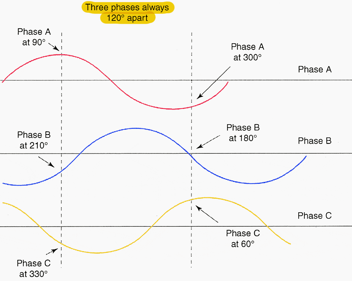

When the load on each phase is identical, the instantaneous power output of the three phases added together is constant. When one phase of a three-phase circuit reaches a peak voltage, another phase is close to zero volts and the third phase is on the return flow. As simple as it is!
So, each phase is 120 degrees out of phase with the other phase. The voltage and current in each phase are 1/180 second, or one-third distance in a cycle behind another phase.
Go back to the Contents Table ↑
1.4 Phase Designations
In the lines trade, it is frequently necessary to trace individual phases to ensure that the correct phase is connected to the correct terminal. Individual phases are named and marked at various locations on the system to keep them apart.
Utilities use various designations and markers, some of which are:
- Red phase, white phase, and blue phase
- Red phase, yellow phase, and blue phase
- A phase, B phase, and C phase
- #1 phase, #2 phase, and #3 phase
- X phase, Y phase, and Z phase
- R phase, S phase, T phase (old designations)
Figure 3 – An example of marked cable phases in red, yellow and blue


Go back to the Contents Table ↑
1.5 Phase Rotation
When a three-phase motor is part of a customer’s load, it is necessary to have the three phases in a sequence, or the motor will run backward. If the hookup to the customer had a B phase, A phase, C phase sequence, the motors would run backward.
Switching any two phases at the transformer will put the phase rotation back in sequence. For example, with a B, A, and C sequence, switching A phase and C phase would give a proper B, C, A (which is A, B, C) sequence.
A test can be made with a rotation meter before the customer load is connected. If the rotation meter shows the supply phases are in proper sequence and the motor runs backward anyway, then the customer will need to reverse two leads on the motor.
Suggested Reading – Main and auxiliary circuit diagrams of three-phase motors
Main and auxiliary circuit diagrams of switching pole-changing three-phase motors
Go back to the Contents Table ↑
1.6 Three-Phase Connections
A three-phase circuit starts at a generator, that’s clear. After generation, these three phases are connected to the input and output sides of transformers throughout the transmission and distribution system. A three-phase circuit is interconnected at the transformers in two ways.
See Figure 4 below.
Connection Way #1
The three phases can be connected in parallel. One end of each of the three coils is connected together to a common point, and the other ends of the three coils are the three-phase connections. This is referred to as wye-connected (named after the letter Y).
A vector drawing showing the three phases interconnected is in the shape of a Y.
Connection Way #2
The three phases can be connected in series, which is referred to as delta-connected (named after the Greek letter delta Δ). A vector drawing showing the three phases interconnected is in the shape of a delta.
Figure 4 – Wye and delta configurations


Go back to the Contents Table ↑
1.7 Wye and Delta Systems
All circuits worked on by the lines trade are fed from a transformer bank somewhere in the system. When the circuit source is from a transformer bank with a delta-connected output, the circuit is a delta system. Similarly, a wye circuit comes from a transformer bank with a wye-connected output.
A three-phase delta circuit consists of three wires. Each wire is a phase 120 degrees out of phase with the other wires. Transformers are connected phase to phase. Lateral taps branching off with two phases are used as single-phase circuits, which feed single-phase transformers and customers.
Connections to the three coils of three-phase transformers or motors are always made based on the standard wye or delta shape, as shown in Figure 5.
Figure 5 – Wye and delta connections in wye and delta shape


Go back to the Contents Table ↑
2. Delta-Connected Systems
2.1 Delta- or Series-Connected Three-Phase System
A delta system is a circuit fed from a delta-connected secondary of a three-phase transformer bank. The transformer bank provides a three-phase delta output with the three phases interconnected as one circuit.
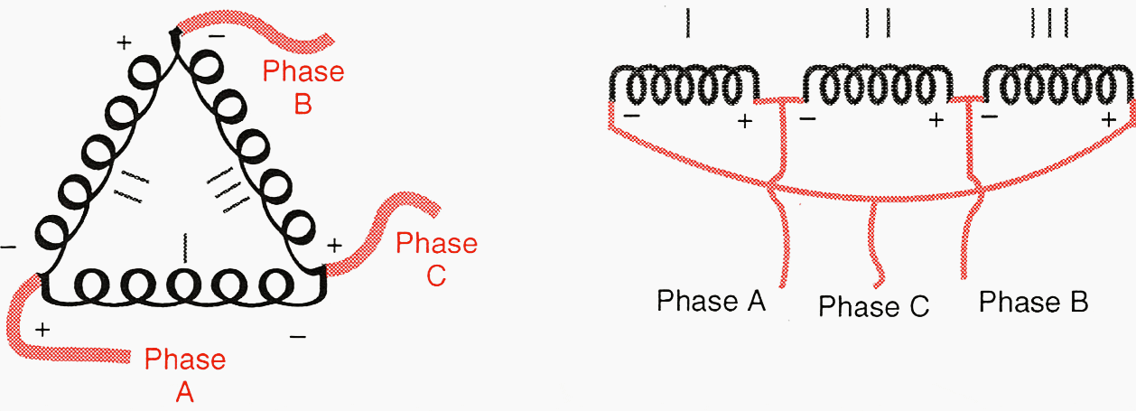
In order to operate, each coil of a transformer must have a potential difference across it. On a delta connection, this can be achieved by connecting each coil phase to phase.
Figure 6 shows how delta connections are made when the coils are in a delta shape and when the coils are side by side.
Figure 6 – Delta configurations

Go back to the Contents Table ↑
2.2 Voltage in a Delta System
The voltage across each coil is the same as the voltage measured from phase to phase. There is a voltage across each coil or between any two phases because each phase is in a different part of the AC cycle.
The three phases are, in fact, always 120 degrees apart.
Go back to the Contents Table ↑
2.3 Current in a Delta System
For this discussion, the phase current is the current in each coil and the line current is the current in each conductor leaving the transformer bank. The current leaving each junction point is the resultant of the current in two phases 120 degrees apart.
The current through each coil is equal to the full-phase current, but the line current leaving each junction point is 1.73 × the phase current in each of the two coils feeding the phase.
Further Study – Overcurrent protection study for power network (solving relay setting miss-coordination)
Overcurrent protection study for power network (solving relay setting miss-coordination)
Go back to the Contents Table ↑
2.4 Return Flow in a Delta Circuit
To complete a circuit, electrical current must return to the source. In a delta circuit, the return flow to the source is in the opposing phase conductors. There is no return flow through the ground.
There is a potential difference between the three phases of a delta circuit, but there is no “theoretical” potential between a phase and ground because going from phase to ground does not complete a delta circuit.
If one of the phases of a delta circuit became grounded, the voltage between the other two phases and ground becomes equal to phase-to-phase voltage. Unless there is a circuit breaker equipped with a ground fault relay, a grounded conductor on a delta circuit will continue to be at a phase-to-phase voltage with the other two phases.
[highlight]Suggested Guide[/highlight1] – Earthing system calculation for 132/11 kV, 1×40 MVA substation of steel factory
Earthing system calculation for 132/11 kV, 1×40 MVA substation of steel factory
Go back to the Contents Table ↑
2.5 Ground Fault Protection in a Delta Circuit
Many, but not all, delta circuits have protection against ground faults. The nature of a delta circuit would not notice a phase-to-ground fault; therefore, a grounding transformer and relays need to be installed.
A grounding transformer is installed in a substation between one phase of a delta circuit and ground. There is normally no voltage difference between a delta phase and ground, so there would be no current flow through the transformer.
During a phase-to-ground fault, the current flowing back to the source will flow through the transformer and send a signal to the ground fault relay. The relay will detect this current and trip out the circuit.
Suggested Course – The Essentials of Relay Protection and Control in Power Systems
The Essentials of Relay Protection and Control in Power Systems
Go back to the Contents Table ↑
3. Wye-Connected Systems
3.1 Wye- or Parallel-Connected Three-Phase System
A wye system is a circuit fed from a wye-connected secondary of a three-phase transformer bank. The transformer bank provides a three-phase wye output with the three phases interconnected as one circuit.
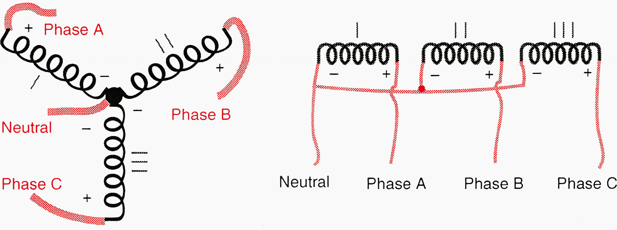
When connected in a wye configuration, each coil of a three-phase transformer is connected between a phase and the neutral. One end of each coil is connected together at a common point, which is the neutral. A voltage will be available at the other ends of the three coils when measured between any two phases. There is also a voltage between each phase and the common point. The three coils are connected in parallel.
Figure 7 shows how wye connections are made when the coils are in a wye shape and when the coils are side by side.
Figure 7 – Wye configurations

Go back to the Contents Table ↑
3.2 Voltage and Current in a Wye System
There are two different voltages available in a wye system: phase-to-phase voltage and phase-to-ground voltage. The phase-to-phase voltage is √3 × the phase-to-neutral voltage. The phase-to-phase voltage is the resultant (vector or algebraic) sum of two phase-to-neutral voltages that are 120 degrees out of phase with each other.
The phase current going through each coil in a transformer is the same as the line current that flows into each phase of the wye circuit. The current flow in a wye circuit is 1/√3, or 58% less than in an equivalent delta circuit.
Go back to the Contents Table ↑
3.3 The Neutral in a Wye System
The neutral is the common point of each transformer winding in a wye system. If the loads on the three phases were equal to each other, there would be no current on the neutral. The neutral carries the sum (algebraic or a vector sum) of the three phase currents back to the source.
With the three phases at 120 degrees, the three currents cancel each other out. The neutral wire can be smaller than the phase wires because it is sized to carry the unbalanced load between phases.
On a single-phase line, the neutral and to a lesser extent the ground is the only path back to the source to complete the circuit.
Some three-wire circuits are actually wye circuits which do not carry a neutral. The need for a neutral is minor when the load is balanced among the three phases.
Transmission and sub-transmission lines have relatively balanced loads and are often wye circuits without a neutral. In some utilities where there is good earth, the neutral is omitted on a distribution feeder because the earth is able to complete the circuit for unbalanced load and fault.
Good Reading – Advice in choosing the right neutral earthing system for your installation
Advice in choosing the right neutral earthing system for your installation
Go back to the Contents Table ↑
3.4 Earth Return System Neutral
There are some locations, mostly in rural, thinly populated areas, where there is no neutral conductor strung on the wye-distribution system. A single-phase circuit would consist of only one conductor strung on a pole. This system uses the earth as the neutral.
A similar approach is used in the electrical system of a car. The metal body of the car is used as the ground wire and is attached to the negative pole of the battery.
It is important to ensure that the down-ground has good physical protection installed where it is accessible to the public.
Related Guide – Handbook for application of neutral earthing resistors (NERs) at the substation
Handbook for application of neutral earthing resistors (NERs) at the substation
Go back to the Contents Table ↑
3.5 Converting from Delta to Wye
Many delta circuits have been converted to wye circuits. There are economical and safety differences between the two systems. When the output connections of a distribution substation transformer are converted from delta to wye, the phase-to-phase voltage will be increased 1.732 (√3) times.
For example, a delta-connected transformer bank that has a phase-to-phase voltage of 2400 volts across each coil of the transformer secondary can be converted to a wye connection by having one end of each 2400 V coil connected to a common point.
Now, the phase-to-phase voltage of the newly connected wye circuit will be 4160 V, and the phase-to-neutral voltage will be 2400 V.
Important Notes:
Usually a conversion involves going to an even higher voltage fed from a new substation transformer. For the same load, the current in each wye-connected phase is reduced by 1/1.732, or 58%. A lower current results in less line loss and less voltage drop.
During conversion, an existing distribution transformer that was connected as phase to phase on the delta circuit can now have the same primary voltage by connecting it phase to neutral on a wye circuit. Note: Usually a conversion involves going to an even higher voltage and installing dual-voltage transformers to reduce the time of customer outage during the changeover.
Single-phase wye-connected transformers require only one cutout and surge arrester instead of the two needed on a delta transformer. Similarly, a single-phase lateral on a: wye system needs only one line switch.
Fuses and circuit breakers trip out quicker due to over-current when there is a good return path to the source. Phase-to-phase short circuits on both wye and delta circuits trip out a fuse quickly because of the good return path to the source through the other phases.
Phase-to-ground faults have a good return path to the source on wye circuits through the multi-grounded neutral. A tree contact would blow a fuse much quicker on a wye system than on a delta system.
Related Course – Learn to Analyse Faults in Power Systems: Theoretical and Real-World Examples
Learn to Analyse Faults in Power Systems: Theoretical and Real-World Examples
Go back to the Contents Table ↑
4. Three-Phase Power
4.1 The Combined Power in Three Phases
When there are voltage and current in each phase of a three-phase circuit, there is also power being delivered. The power delivered by each phase will be 120 degrees out of phase with the other phases. In other words, the power delivered by one phase could be at its peak when the power delivered by another phase is one-third farther into the cycle and the power delivered by the third phase is two-thirds farther into the cycle.
Therefore, the total power in a balanced three-phase system is not simply three times the power of one phase. The square root of three, which is 1.73, times the power in one phase will give the power in three phases.
When the load is unbalanced, the load in each phase needs to be measured individually and the average value is put into the equation. The power factor must be known to calculate the true power delivered by a three-phase system.
Useful Notes – Electrical Power Notes and Formulas For Students
Go back to the Contents Table ↑
4.2 Field Calculations
Converting amperes in a circuit to kilovolt-amperes (kVA) and converting kVA into amperes per phase are sometimes valuable tools in the field. Field calculations are valuable when balancing three-phase circuits. The ampere loading of a phase should be converted to kVA to determine which transformers to transfer over to another phase.
Before working live line on a transmission circuit where jumpers are going to be installed, it is valuable to know the expected load on a phase. The controlling station can give the total load on the circuit, which can be converted to amperes per phase using field calculations.
To determine the total load on a transformer, field calculations can convert amperes per phase to kVA.
Useful Course – Fundamentals of Instrument and Electric Power Metering in Utilities and Industry
Fundamentals of Instrument and Electric Power Metering in Utilities and Industry
Go back to the Contents Table ↑
4.3 Calculations Involving Power
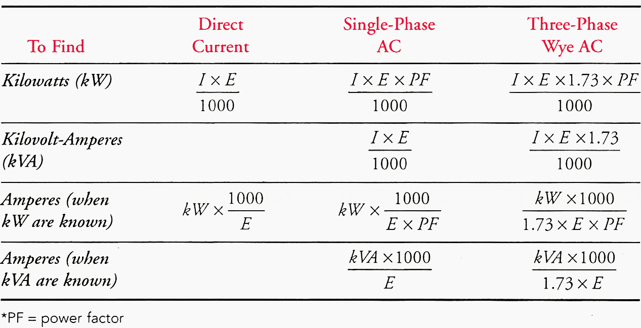
Table 1 gives formulas used to calculate power in three-phase and single-phase circuits. Calculations for field applications use the kVA formulas. Calculations involving three-phase power use line-to-line (phase-to-phase) voltage. The value of the square root of three is normally 1.73.
Table 1 – Power Formulas

Go back to the Contents Table ↑
4.4 Calculations with “Handy Numbers”
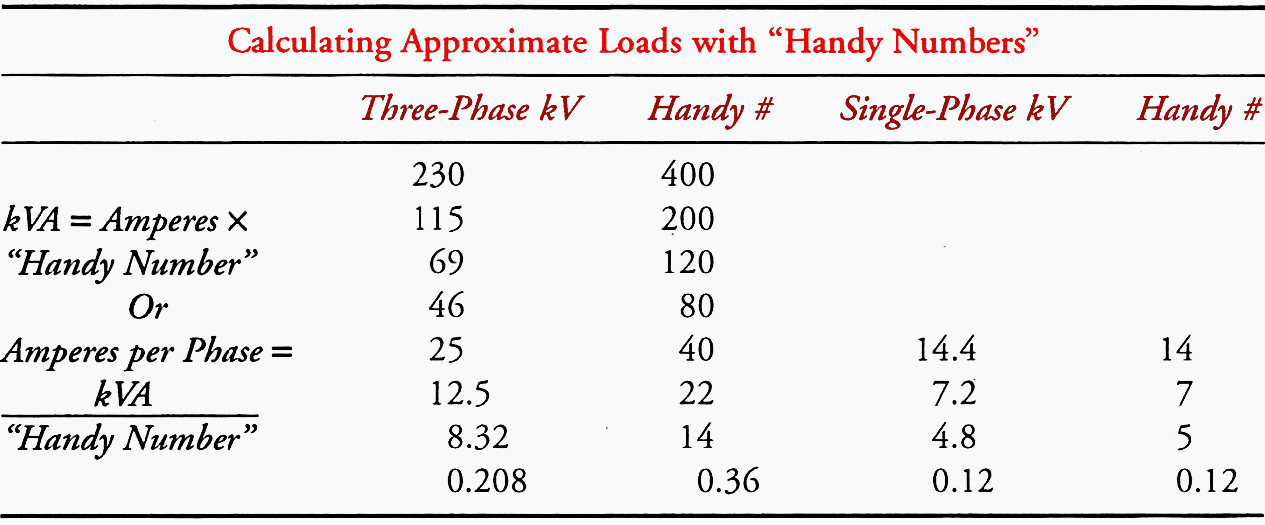
To be able to do the power calculations quickly in the field, a “Handy Number” can be used for approximations (Table 2).
- Approximate kVA = amperes × “Handy Number’
- Approximate amperes per phase = kVA / “Handy Number”
Table 2[/highlight2] – Examples of “Handy Numbers” for Some Voltage Systems

Go back to the Contents Table ↑
4.5 Examples Using “Handy Numbers”
Question #1
One phase of an 8.3/4.8 kV feeder has 80 A more load than the other two phases. To balance the feeder, how many kVA should be transferred to the other two phases?
Answer #1
Using a “Handy Number,” which is 5 for a 4.8 kV single-phase line, × 80 A = 400 kVA. Therefore, 200 kVA should be transferred to each of the other two phases.
Question #2
Load on each of the three phases of a 120/208 50 kVA pad mount transformer bank are 150 A, 170 A, and 140 A. Is the transformer overloaded?
Answer #2
The average load on the three phases is (150+170+140) / 3 = 153 A. Using the “Handy Number,” which is:
0.36 for 120/208 V service, × 153 = 55 kVA.
The transformer is only slightly above its rating, but the load should be balanced more between the three phases to prevent one transformer winding from being overloaded.
Go back to the Contents Table ↑
Source: Electrical essentials for powerline workers by W.V. Soelen


Good day!
(I confess) I struggled a bit to relate Fig,1, Fig, 2 and Section 1.3 above.
First, from this:
(Quote from mid-paragraph 1 of Sec. 1.3)
“… The first vertical line in Figure 2 shows the values being generated in Figure 1.
Phase A, at 90 degrees , is generating at the maximum value, phase B, at 210 degrees, is climbing towards the zero value, and phase C, at 330 degrees, is approaching the maximum return or negative value.” (End of quote)
I almost convinced myself that the labels of the curves for Phases B & C were swapped/interchanged; then upon further reading I thought they should be kept, but the degrees (210 & 330) of the Phase B and Phase C should be interchanged, looking at the waveform position. Could I be wrong/confused?
Then from this:
(Quote from 3rd paragraph)
The second vertical line shows what is happening to the power generated in each phase when phase A is 120 degrees (one-third of the way) into the cycle, phase B would be 240 degrees (two-thirds of the way) into the cycle, and phase C would be at 360 degrees (at the end, which is also the beginning) of the cycle. (End of quote)
The description here made perfect sense by itself and without relating to the Figure 2. Is it possible, that the referenced 2nd vertical line is not showing on the Figure 2. The diagram, at least on my browser, has only 2 lines, the 2nd which is also clearly and understandably labelled for each curve A/B/C as at 300/180/60 degrees respectively.
If my perception on the 1st case is misconstrued, I would appreciate any clarification.
The second may be a case of poor rendition on my browser not showing another 2nd vertical line.
Regards, and Compliments for a great informative site!!
A review and reinforcement of previous knowledge. Thanks mucho
Very informative presentation. Could you please provide a simplified sketch of the phase winding distribution as applied to the generator?
Thanks so much for your inspiring details, I am very interested in electricity,