
Estimated Study Time: 14 minutes
Basic principles of three phase systems
Although single-phase electricity is used to supply common domestic and office electrical appliances, three phase alternating current (a.c.) systems are almost universally used to distribute electrical power and to supply electricity directly to higher power equipment.
 Basic three phase power measurements explained in details (photo credit: d.mike36 via Flickr)
This technical article describes the basic principles of three phase systems and the difference between the different measurement connections that are possible.
- Three phase systems
- Power measurements
- Single-Phase wattmeter Connection
- Single-Phase Three-Wire Connection
- Three Phase Three-Wire Connection (Two Wattmeter Method)
- Three Phase Three-Wire Connection (Three Wattmeter Method)
- Blondel’s Theorem: Number of Wattmeters Required
- Three-Phase, Four-Wire Connection
- Configuring Measurement Equipment
Three Phase Systems
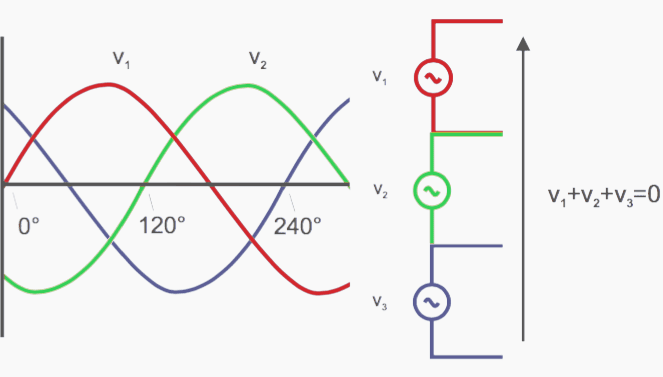
Three phase electricity consists of three AC voltages of identical frequency and similar amplitude. Each AC voltage ‘phase’ is separated by 120° from the other (Figure 1).
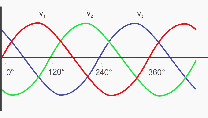
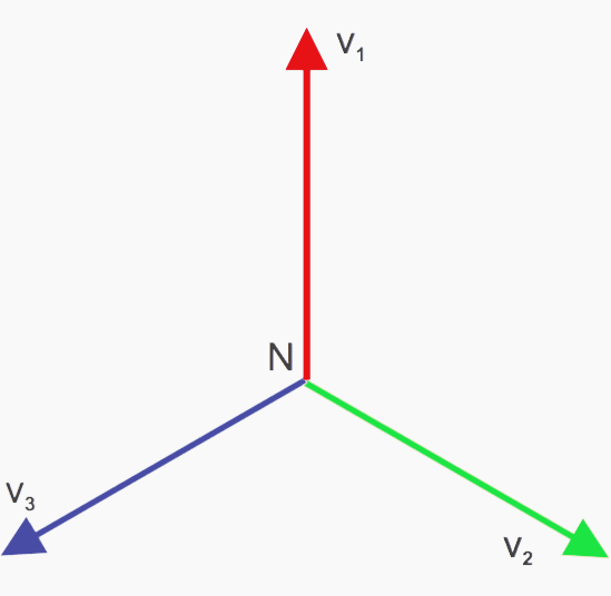
This can be represented diagrammatically by both waveforms and a vector diagram (Figure 2).
Why using three phase systems? For two reasons:
- The three vector-spaced voltages can be used to create a rotating field in a motor. Motors can thus be started without the need for additional windings.
- A three phase system can be connected to a load such that the amount of copper connections required (and thus the transmission losses) are one half of what they would otherwise be.
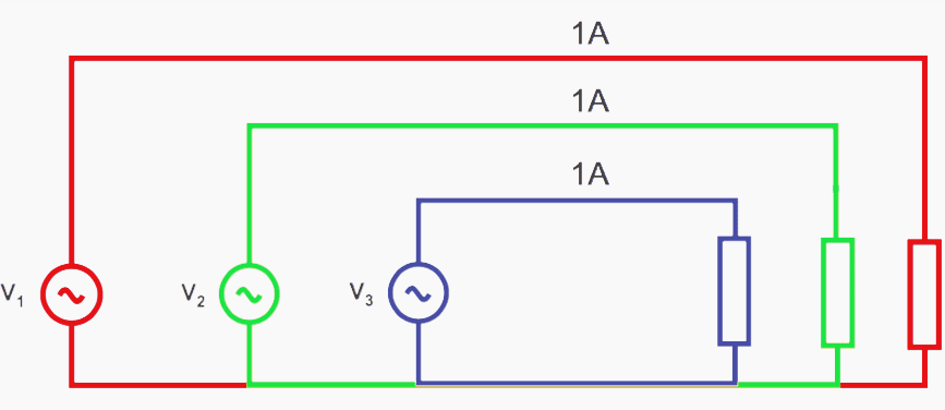
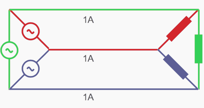
Consider three single-phase systems each supplying 100W to a load (Figure 3). The total load is 3 × 100W = 300W. To supply the power, 1 amp flows through 6 wires and there are thus 6 units of loss.

Alternatively, the three supplies can be connected to a common return, as shown in Figure 4. When the load current in each phase is the same the load is said to be balanced. With the load balanced, and the three currents phase shifted by 120° from each other, the sum of the current at any instant is zero and there is no current in the return line.
In a three phase 120° system, only 3 wires are required to transmit the power that would otherwise require 6 wires. One half of the copper is required and the wire transmission losses will be halved.
Go back to Three phase power measurements ↑
Wye or Star Connection
A three phase system with a common connection is normally drawn as shown in Figure 5 and is known as a ‘wye’ or ‘star’ connection.
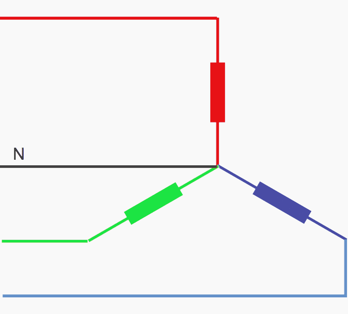
The common point is called the neutral point. This point is often grounded at the supply for safety reasons. In practice, loads are not perfectly balanced and a fourth ‘neutral’ wire is used to carry the resultant current.
Go back to Three phase power measurements ↑
Delta Connection
The three single-phase supplies discussed earlier could also be connected in series. The sum of the three 120° phase shifted voltages at any instant is zero. If the sum is zero, then both end points are at the same potential and may be joined together.
The connection is usually drawn as shown in Figure 7 and is known a delta connection after the shape of the Greek letter delta, Δ.
Go back to Three phase power measurements ↑
Wye and Delta comparison
The Wye configuration is used to distribute power to everyday single-phase appliances found in the home and office. Single- phase loads are connected to one leg of the wye between line and neutral. The total load on each phase is shared out as much as possible to present a balanced load to the primary three phase supply.
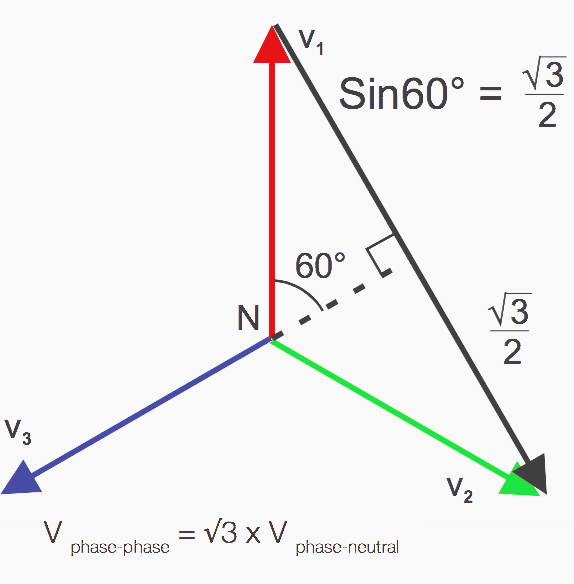
The wye configuration can also supply single or three phase power to higher power loads at a higher voltage. The single- phase voltages are phase to neutral voltages. A higher phase to phase voltage is also available as shown by the black vector in Figure 8.
The delta configuration is most often used to supply higher power three phase industrial loads. Different voltage combinations can be obtained from one three phase delta supply however, by making connections or ‘taps’ along the windings of the supply transformers.
The center-tap may be grounded at the transformer for safety reasons. 208V is also available between the center tap and the third ‘high leg’ of the delta connection.

Go back to Three phase power measurements ↑
Power Measurements
Power is measured in ac systems using wattmeters. A modern digital sampling wattmeter, such as any of the Tektronix power analyzers, multiplies instantaneous samples of voltage and current together to calculate instantaneous watts and then takes an average of the instantaneous watts over one cycle to display the true power.
In order for the power analyzer to give good results, you must be able to correctly identify the wiring configuration and connect the analyzer’s wattmeters correctly.
Go back to Three phase power measurements ↑
Single-Phase Wattmeter Connection
Only one wattmeter is required, as shown in Figure 10. The system connection to the voltage and current terminals of the wattmeter is straightforward. The voltage terminals of the wattmeter are connected in parallel across the load and the current is passed through the current terminals which are in series with the load.

Go back to Three phase power measurements ↑
Single-Phase Three-Wire Connection
In this system, shown in Figure 11, the voltages are produced from one center-tapped transformer winding and all voltages are in phase. This is common in North American residential applications, where one 240 V and two 120V supplies are available and may have different loads on each leg.
To measure the total power and other quantities, connect two wattmeters as shown in Figure 11 below.
Go back to Three phase power measurements ↑
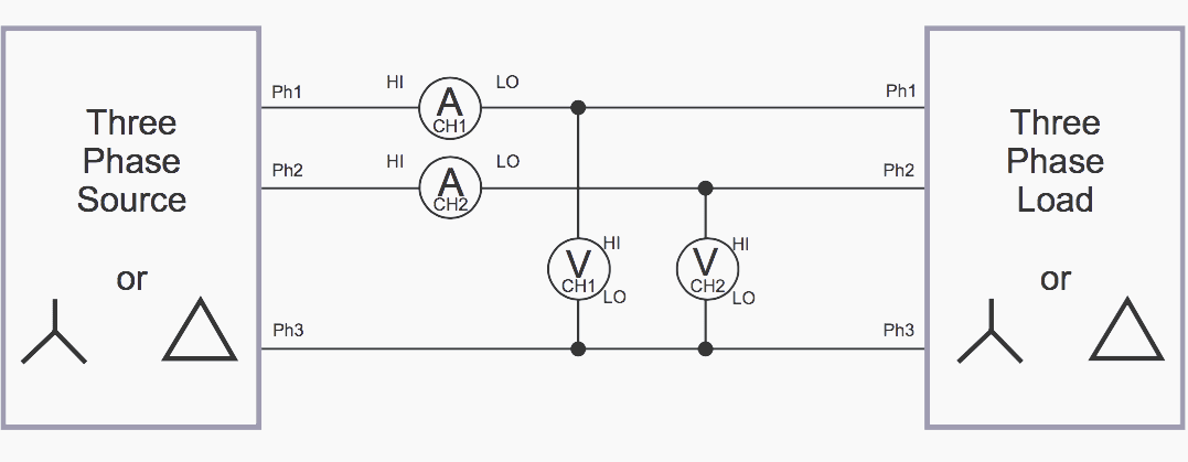
Three Phase Three-Wire Connection (Two Wattmeter Method)
Where three wires are present, two wattmeters are required to measure total power. Connect the wattmeters as shown in Figure 12. The voltage terminals of the wattmeters are connected phase to phase.
Go back to Three phase power measurements ↑
Three Phase Three-Wire Connection (Three Wattmeter Method)
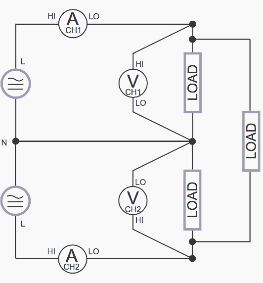
Although only two wattmeters are required to measure total power in a three-wire system as shown earlier, it is sometimes convenient to use three wattmeters. In the connection shown in Figure 13 a false neutral has been created by connecting the voltage low terminals of all three wattmeters together.

The three-wire, three-wattmeter connection has the advantages of indicating the power in each individual phase (not possible in the two-wattmeter connection) and phase to neutral voltages.
Go back to Three phase power measurements ↑
Blondel’s Theorem: Number of Wattmeters Required
In a single-phase system there are just two wires. Power is measured using a single wattmeter. In a three-wire system, two wattmeters are required as shown in Figure 14.
In general, the Number of Wattmeters Required = the Number of Wires – 1

Proof for a three-wire wye system
The instantaneous power measured by a wattmeter is the product of the instantaneous voltage and current samples.
- Wattmeter 1 reading = i1 (v1 – v3)
- Wattmeter 2 reading = i2 (v2 – v3)
Sum of readings W1 + W2 = i1v1 – i1v3 + i2v2 – i2v3 = i1v1 + i2v2 – (i1 + i2) v3
(From Kirchoff’s law: i1 + i2 + i3 = 0, so i1 + i2 = -i3)
Go back to Three phase power measurements ↑
Three Phase, Four-Wire Connection
Three wattmeters are required to measure total watts in a four-wire system. The voltages measured are the true phase to neutral voltages. The phase to phase voltages can be accurately calculated from the phase to neutral voltages’ amplitude and phase using vector mathematics.
A modern power analyzer will also use Kirchoff’s law to calculate the current flowing in the neutral line.
Go back to Three phase power measurements ↑
Configuring Measurement Equipment
For a given number of wires, N, N-1 wattmeters are required to measure total quantities such as power. You must make sure you have sufficient number of (3 wattmeter method) channels, and connect them properly.
The formulas are selected based on the wiring configuration, so setting the wiring is critical to get good total power measurements. A power analyzer with vector mathematics capability will also convert phase to neutral (or wye) quantities to phase to phase (or delta) quantities.
The factor √3 can only be used to convert between systems or scale the measurements of only one wattmeter on balanced, linear systems.
Understanding wiring configurations and making proper connections is critical to performing power measurements. Being familiar with common wiring systems, and remembering Blondel’s Theorem will help you get the connections right and results you can rely upon.
Go back to Three phase power measurements ↑
Reference // The Fundamentals of Three Phase Power Measurements – Application Note by Tektronix
Related electrical guides & articles


Edvard Csanyi
Hi, I'm an electrical engineer, programmer and founder of EEP - Electrical Engineering Portal. I worked twelve years at Schneider Electric in the position of technical support for low- and medium-voltage projects and the design of busbar trunking systems.I'm highly specialized in the design of LV/MV switchgear and low-voltage, high-power busbar trunking (<6300A) in substations, commercial buildings and industry facilities. I'm also a professional in AutoCAD programming.
Profile: Edvard Csanyi

1. When the power company runs 220/440 to your property do they ground at the pole?
2. Do they ground the neutral wire at the pole, then run wires to the building?
3. when the wires are run a couple hundred feet from the pole to the shed how do they make ground measurements?
4. What is the correct resistance from neutral to earth ground?
What is the effect of the unbalanced load current(3 phase Y or Delta) in a 3-phase wattmeter?
I don’t know about a single 3phase watt meter.
I do have 3 individual watt meters if properly hooked up I would measure the unbalanced redistribution of currents. Effect of unbalanced could be a burnt motor or a problem happening sometime in the future. If it is a situation where you are adding additional loads, motors, transformers you will be able to possibly bring (it to) balance. the best design today is always modified by later developments. To keep designs in balance the designer and installer need to work with updated drawings adding notes to all changes.
You have one error in this artikel.
On figure 5 is delta connection. It should be picture of star connection.
Excellent catch! Mistake removed :)