
3-phase transformer and harmonics
The way in which a three-phase transformer responds to harmonics depends on the connection configuration used. For a star-star configuration, any imbalance in the phase currents results in the star point being electrically displaced and the phase to neutral voltages unequal.
 How a three-phase power transformer responds to harmonics (on photo: Fluke 435 series II power quality and energy analyzer; credit: fluke-ireland.ie)
Triple-N harmonic currents cause harmonic voltages to appear on both primary and secondary phase-to-neutral voltages and as ripple on the star point voltage. If the primary is fed by a four-wire system, i.e. star point is connected to neutral, the voltage distortion is removed, but a harmonic current flows in the primary neutral, so exporting the distortion onto the supply system.
In the delta-star configuration, the unbalanced and triple-N currents circulate in the delta winding of the primary and do not propagate onto the supply system. This configuration is the one most commonly used for distribution transformers.
Note that all other harmonics do propagate back onto the supply and can be widely distributed as a result. As would be expected, the lower harmonics are the most troublesome because they are larger, less attenuated by the system impedance and more difficult to remove at source.
All harmonics, whether propagated or not, cause increased losses in the transformer winding and core. Circulating currents do no useful work, but cause excess loss and increased temperature in the winding. Magnetic and eddy losses are increased at the higher harmonic frequencies.
The transformer eddy current loss increase can be calculated by:
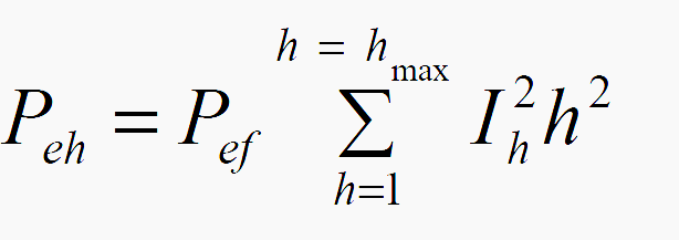
where:
- Peh is the total eddy current loss
- Pef is the eddy current loss at fundamental frequency
- h is the harmonic order
- Ih is the RMS current at harmonic h as a percentage of rated fundamental current
and the stray losses can be calculated by::
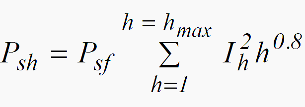
where:
- Psh is the total eddy current loss
- Psf is the eddy current loss at fundamental frequency
- h is the harmonic order
- Is is the RMS current at harmonic h as a percentage of rated fundamental current
They also assume that the source impedance is constant for all harmonics which is not so in practice. Large transformers often have parallel windings in which it can be difficult to achieve good load sharing. This problem is compounded when harmonics are present because generally they will not share in the same proportion as the fundamental. Computer modelling techniques are now available to assist in transformer design.
Note that transformers that are required to supply harmonic generating loads need to be carefully and completely specified so that the manufacturer can take appropriate measures to control losses.
Assessing transformer loss in harmonics high environment
Reference // Electrical Design – A Good Practice Guide by Copper Development Association


I appreciate your efforts