
System Commissioning
No matter the approach, it is necessary that the testing engineers who will be responsible for commissioning the switchgear have a solid comprehension of the equipment that will be utilized and the various modes of operation that will be utilized. It is also extremely important to ensure that both the employees and the plant are safe while commissioning, and the best way to do this is through careful planning as well as the recording of both procedures and safety measures.
 Thumb rules, dos and don’ts in MV/HV switchgear testing and commissioning
Since there must not under any circumstances be a rush on the commissioning time, the planning for the project must take into consideration the possibility of delays occurring in the early stages of the project’s timeline.
Commissioning should also have a sufficient budget allocated to it. A common provision for commissioning is one percent to one and a half percent of the total cost of the electrical system.
1. Standards Covering Switchgear Testing
The following standards cover switchgear testing:
- IEC 62271-100: High voltage switchgear and control gear – HV alternating current circuit breakers
- IEC 62271-1: High-voltage switchgear and controlgear – Part 1: Common specifications for alternating current switchgear and
- IEC 62271-101: High-voltage switchgear and controlgear – Part 101: Synthetic testing
- IEC 62271-203: High voltage switchgear and control gear – Gas-insulated metal-enclosed switchgear for rated voltages of 72.5 kV and above
- IEC 60060: High voltage test techniques
- IEC 60480: Specifications for the re-use of sulphur hexafluoride (SF6) and its mixtures in electrical equipment
- controlgear
Go back to the Contents Table ↑
2. Switchgear Type tests
The following switchgear test are considered as type tests:
- Dielectric measurement.
- Temperature rise tests.
- Making and breaking tests.
- Mechanical endurance.
Let’s have a word about each test:
2.1 Dielectric Measurements
Is switchgear able to withstand the voltage stresses?
Dielectric measurements indicate that switchgear with a specific voltage rating can withstand the voltage stresses expected in service from switching operations or lightning surges. The switchgear is subjected to one-minute power frequency voltage withstand testing. A voltage greater than the rated voltage of the switchgear is used to validate proper clearances and insulation strength between phases, across open contacts, and between phase and earth.
The tests also examine the withstand capabilities of switchgear closing and opening resistors, GIS designs, and grading capacitors. When calculating the test voltage to be used, a suitable margin between the withstand voltage levels and transitory overvoltages that may occur during switching operations must be provided for.
Furthermore, the performance of asymmetric electrode morphologies at various high test voltage polarities must be examined.
Switchgear operating at high altitude, where the air density is lower, requires, for instance, larger switchgear clearances to be accounted for in designs. To account for the higher withstand voltage of air at sea level, the type test voltage is also raised.
Type testing should be carried out under the most unfavorable conditions, as the dielectric strength of SF6 fluctuates with density.
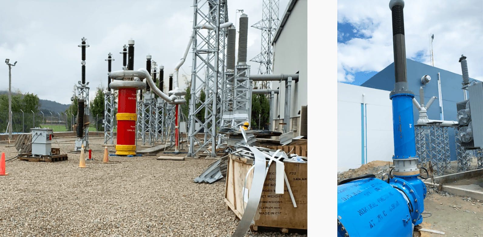
Figure 1 – Dielectric tests performed on GIS switchgear

Tests on outdoor gear can be carried out in either dry or wet environments, depending on the requirements of the product. As a technique of ensuring suitable insulator profiles and creepage distances, the wet conditions make an attempt to take into account the effects of water cascading down the switchgear porcelain insulators. This is done by taking into account the wet circumstances.
The performance of insulators in dirty or low-temperature ice circumstances also needs to be evaluated and is the subject of particular agreements between the client or his engineer and the switchgear or insulator makers.
A standard test consists of applying test voltages between each phase and earth in turn 15 times while the circuit breaker is closed and the remaining phases are earthed. Normally, a standard 1.2/50 s impulse voltage wave shape is used to simulate lightning strike conditions, and a 250/2500 s wave shape is used to simulate switching surges.
Additionally, test voltages are provided across each set of open circuit breaker contacts. This is done in addition to the previous step. If there are not more than two flashovers during any one series of 15 tests, then the overall test is regarded to have been successful. However, these discharges can only take place in self-restoring insulation (such as air, oil, or SF6 gas), therefore this requirement must be met.
In most cases, an inability to recover from a test failure caused by a breakdown of solid insulation is the outcome of the breakdown.
In the event that it is necessary, more investigations to verify this could be carried out.
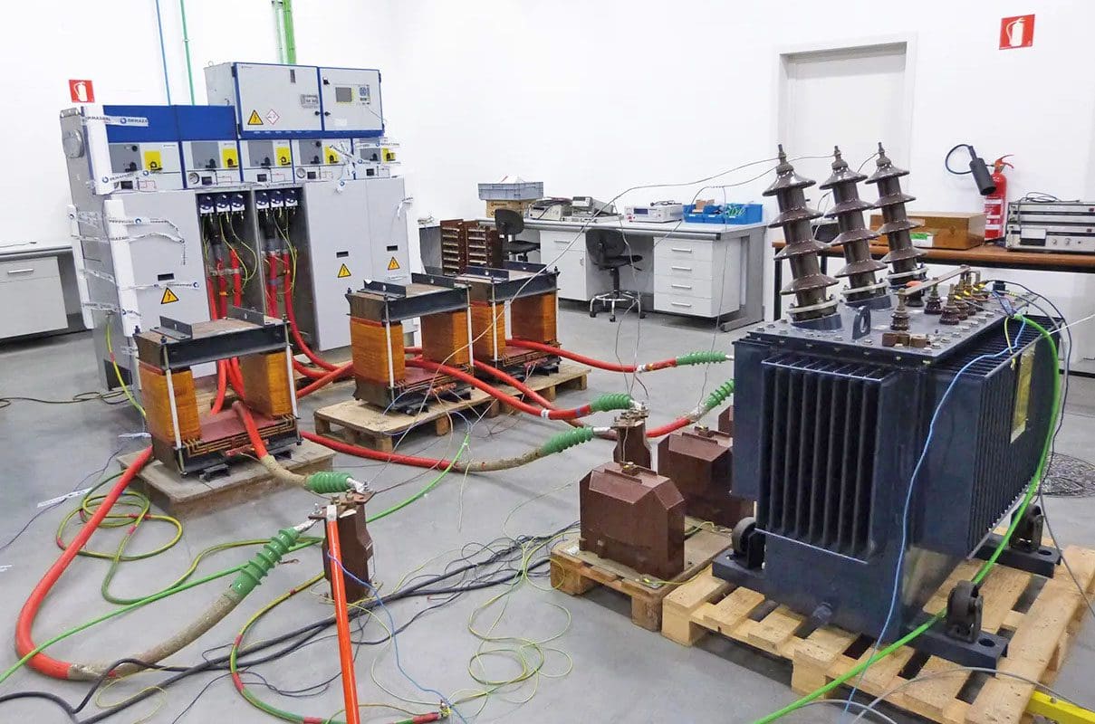
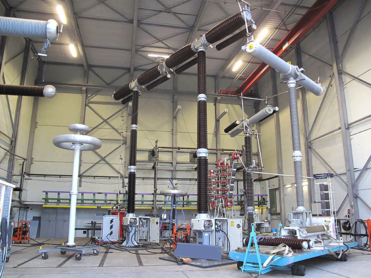
Figure 2 – High-Voltage Testing and Partial Discharge Measurements in GIS-Air Connection GIS Bushing
The above GIS Test Transformers typically either use oil or SF6 as their insulating medium. Oil transformers have significantly higher power outputs and tuning ranges, however they cannot be connected directly to the GIS bus and must utilize external air connections. SF6 transformers with direct SF6 bus to the test object are the preferred method of connection for PD measurements.
When the switchgear is subjected to rated voltages higher than 300 kV, a bias test is carried out on it. The design of the circuit breaker is tested under the conditions of a lightning strike with the switchgear in the open position and the waveform peaks in the opposite polarity by applying a power frequency to one terminal of the circuit breaker and a lightning impulse to the other terminal. This is done so that the design can be validated under these conditions.
In most cases, partial discharge tests are not required to be performed as a component of a full circuit breaker assembly type examination. However, partial discharge testing is especially useful for switchgear systems that include components that have solid insulation.
The oscillograph traces might be used to make an effort at determining the voltage levels that were present at the beginning and end of the discharge. An examination of the traces enables a determination to be made as to whether the failure was caused by voids in the insulation, corona discharge, or some other factor.
During the testing of the power frequency overvoltage, another option is to determine the maximum discharge level, which is measured in picocoulombs.
Suggested Video – Voltage withstand test on a GIS 123 kV
Interference from electromagnetic fields can be caused by external discharges. Corona breakdown can be observed visually in a dimly lit laboratory, and the voltages at the moment of genesis and extinction can be measured. Radio noise levels that are the result of external discharges are measured in decibels (dB) above a reference level that is expressed in microvolts (μV).
According to IEC 62271, Table 1 outlines the lightning impulse and switching overvoltage levels that circuit breakers are rated for.
Table 1 – Circuit breaker rated lighting impulse & switching overvoltage levels (IEC 62271)
Note: Per unit maximum permissible switching overvoltage = peak value (kV peak) / {rated value (kV rms) × √2 /3}
Go back to the Contents Table ↑
2.2 Temperature Rise Tests
Can closed switchgear contacts handle higher temperature?
When the switchgear contacts are closed, the current that should be passing through them is the one that corresponds to the correct power frequency rating. In order to establish the continuous ultimate temperature rise at various temperature sensor positions on the switchgear, plots of temperature against time are recorded.
The many switchgear components each have their own unique set of standard permissible temperature rise limits.
These are based on previous experiences of temperatures at which it is safe to work (ambient plus the maximum temperature rise), which give switchgear performance that is reliable over the long term. If temperature limitations are surpassed, insulating and interrupter oil may begin to lose its qualities (a rule of thumb that is often used states that the life of insulation is cut in half for every 10 degree Celsius increase in operation temperature).
The lifespan of paper insulation in particular is significantly shortened when exposed to high temperatures.
When switchgear from a standard manufacturer is installed in panels that have been custom-built, extra care and attention must be made to ensure that appropriate heat transfer is allowed to occur so that temperature rise limitations are not exceeded. Many manufacturers of low voltage switchgear include specifics regarding the required busbar diameters and enclosure dimensions in their product documentation.
These are essential for ensuring appropriate heat transfer and dissipation.
Figure 3 – MV Switchgear Temperature Rise Tests
If the type testing is going to yield relevant results for the particular application, it is very necessary that the real enclosure that is going to be used in practice also be used during the type testing. The acceptable rise in temperature is based on the maximum ambient temperature being 40 degrees Celsius and the average ambient temperature being 35 degrees Celsius.
When the rating of equipment is established for operation in hot climates with ambient temperatures that are higher than these values, appropriate derating factors must be applied to the existing rating of the equipment.
Go back to the Contents Table ↑
2.3 Circuit Breaker Making and Breaking Tests
Are CB mechanical and insulating parts same after testing?
IEC 62271 specifies the various making and breaking type tests that must be carried out on circuit breakers at the rated voltage, the rated current, and the short circuit current. The testing facility has a unique configuration so that it can handle the short circuit powers that are involved. In situations where synthetic tests to IEC 62271-101 are utilized to replicate field conditions, performing full three phase testing is impractical for values that are greater than approximately 8 GVA at 275 kV.
After the original design and testing work has been done by the manufacturer, such tests are therefore generally carried out at recognized and independent short circuit test facilities.
After all of the test sequences have been completed, the mechanical and insulating parts of the circuit breaker need to be in basically the same condition as they were before the test duty. It may be essential to disassemble the circuit breaker in some circumstances, such as when dealing with sealed-for-life GIS or vacuum switchgear, in order to visually evaluate the results of the testing.
Figure 4 – Circuit Breaker Making and Breaking Tests
Go back to the Contents Table ↑
2.3.1 Terminal Faults
Close-up terminal fault tests involve exposing the circuit breaker in stages to short circuit currents that are 10%, 30%, 60%, and 100% of their rated value. Additionally, the circuit breaker is subjected to an asymmetrical short circuit that is 100% of its rated value. This is done to simulate a close-up fault, such as one that might occur in practice as a result of earths being left on busbars after maintenance.
It is common practice to leave a gap of three minutes between each break or opening (O) operation, and a perfectly timed duty cycle that includes three breaks is sometimes written as ‘O–3–O–3–O‘. In most cases, the time gap is between 2 and 10 minutes long, and it never goes below 2 minutes or above 10 minutes.
See Figure 5.
Figure 5 – Close-up short line fault

The ability of the circuit breaker to make the circuit is validated by close and open (CO) tests conducted at full short circuit current. The notation ‘O–3–CO–3–CO‘ would be used to describe a typical duty cycle. The purpose of this is to show that the closing mechanism, contacts, and interrupter design, as well as the closing speed, are adequate to counteract the effects of short circuits.
Under conditions of maximum asymmetry in one phase, such forces must contend with their greatest challenge. By altering the amount of time that passes between the first open and the close/open operation, it is possible to mimic the additional stresses that are imposed on the circuit breaker as a result of auto-reclose protection systems as well as the circuit breaker’s capacity to handle such forces.
Due to the fact that the fault is not stopped by all three poles of the circuit breaker at the same time, the first phase-to-clear power frequency recovery voltage suffers a voltage increase that is up to 1.5 times higher than the normally rated voltage to earth.
See Figure 6.
Figure 6 – Power frequency recovery voltages for a three-phase fault in a solidly earthed system

Note that the R-phase is the first pole to clear. Recovery voltage across first pole to clear is 1.5 × 2 × 2 phase voltage (transient voltage doubling and 1.5 first pole to clear factor).
Go back to the Contents Table ↑
2.3.2 Line Faults
At higher voltage levels (over 72.5 kV), switching surges can create very high transient recovery voltages. These surges are caused by an exchange of energy between the impedances on the source side and the faulted line side of the circuit breaker. Given the potential for many restrikes of the arc, this constitutes a challenging test scenario with the potential to cause the circuit breaker to fail.
The short line fault test circuit is responsible for simulating the impedances and employing a duty cycle of ‘O–3–O–3–O’ in order to conduct a series of breaking tests at 90% and 75% of the rated short circuit breaking current in addition to the suitable prospective TRV.
Suggested Webinar – Performing Switching and Insulation Studies: Transient Recovery Voltage (TRV) Studies
Go back to the Contents Table ↑
2.3.3 Capacitive Switching
A sequence of capacitive current switching test duties includes breaking 100% and 20% to 40% of the rated capacitive charging current of the overhead line or cable (usually at rated voltages over 72.5 kV for overhead line charging currents and above 24 kV for cable circuits). This is done in order to test the switching capabilities of the capacitive charging current.
Take note that these tests might be particularly significant for circuit breakers that operate harmonic filters, power factor correction installations, or even very extensive cable networks.
Further Reading – 1-phase and 3-phase capacitive-load switching in T&D systems
Single phase and three phase capacitive-load switching in transmission & distribution systems
Go back to the Contents Table ↑
2.3.4 Out-Of-Phase Tests
These determine the circuit breaker’s ability to terminate circuit connections between, say, out-of-phase generators under asynchronous situations. The resulting recovery voltage (up to 2.5 times the normal-rated power frequency voltage) is significantly larger than that for the close-up terminal fault situation, which has a fault current that is only around 25% of the rated short circuit breaking current.
Two opening operations (O and O) at 20% to 40% of the rated out-of-phase breaking current are performed, followed by one close-open (O and CO) test at the maximum rated out-of-phase breaking current.
According to the superseded IEC 56 guidelines (no equivalent recommendation is given in the later IEC 62271-100), a 10 ms DC component decay results in a current peak 1.8 times the symmetrical short circuit peak.
Go back to the Contents Table ↑
2.3.5 Short Time Currents
Simply talking, circuit breakers, busbars, disconnectors, CTs, and other electrical components are put through short time withstand current testing to see whether or not they are able to survive through-fault current without being damaged. It is also possible to set up the initial peak test current so that it reaches the level of a fully asymmetrical situation that has been predetermined.
In most cases, the standardized time durations of one or three seconds have been derived from what is thought regarded as a reasonable amount of time needed for backup protection to operate in real-world scenarios.
Suggested Video – Electrical and Insulation Testing of HV Gas Insulated Switchgear
Go back to the Contents Table ↑
2.4 Switchgear Mechanical Endurance
After the circuit breaker or switching device has been put through a series of up to 2000 open–close operations, any excessive wear as well as the following are inspected at the conclusion of the test:
- Closing/opening and speed
- Control circuit power consumption
- Duration of opening and closing command impulses
- Resistance of main circuit
- Time spread between pole operations
- Trip circuit power consumption
- Enclosure and interrupter head tightness
- Main contact condition
- Operating device times re-charging times
- Auxiliary contact condition
- Gas densities (or pressures)
- Rigidity of structure
Additional tests over a wide temperature range may also be carried out.
Suggested Reading – The art of the switchyard design: Handpicked details you must consider
The art of the switchyard design: Handpicked details you must consider without fail
Go back to the Contents Table ↑
3. Switchgear Routine Tests
The following switchgear test are considered as routine tests:
- Power frequency withstand.
- Voltage withstand on control and auxiliary circuits.
- Measurement of resistance of main circuit.
- Mechanical operating tests.
- Visual checks.
Go back to the Contents Table ↑
4. On-Site tests
It is essential to ensure that equipment is not overstressed by conducting inappropriately repeated tests of the same type or routine under insufficient environmental conditions. Nevertheless, it is crucial to check that neither the transport nor the erection of the MV/HV switchgear equipment resulted in any damage. It may be essential to ask the manufacturer to observe the site erection process and/or to assist in the process of commissioning the switchgear, although this will depend on the relative amount of site assembly that is required.
It is of the utmost importance to conduct an analysis of the dielectric strength of the GIS components’ whole assembly after they have been brought to the construction site in separate pieces and then welded together. This is done with the intention of preventing problems such as incorrect fastenings, damage incurred during transportation or handling, storage, the presence of foreign bodies, etc.
Table 2 provides specific information on the AC withstand test voltages that are administered to GIS sites for one minute. The voltages are applied one at a time between each phase conductor and the enclosure, with the other phase conductors being connected to the enclosure’s earthed connection. After that, separate site dielectric tests should not be performed on the insulation that is located between the phase conductors.
Impulse tests, which include three of each polarity’s impulses, can also be carried out at the levels outlined in Table 19.6.
Table 2 – Site dielectric test voltages for GIS switchgear

Switchgear site tests generally include:
General checks:
- Assembly to manufacturer’s drawings
- Tightness of terminal connections, piping, junctions and bolted joints
- Painting and corrosion protection
- Cleanliness
Electrical circuit checks: Insulation checks Dielectric strength of insulating oils (see IEC 60296) and level, SF6 quality, humidity content (see IEC 60376) filling pressure or density except for sealed apparatus
Mechanical tests:
- Operating circuits (hydraulic, pneumatic, spring charged)
- Consumption during operation
- Verification of correct rated operating sequence (recharging, etc.)
Time quantities:
- Closing and opening times
- Operation and control of auxiliary circuits
- Recharging time of operating mechanism after specified sequence
- Checks on specific operations
Electrical tests:
- Dielectric tests
- Resistance of main circuit
A typical MV circuit breaker maintenance inspection report proforma is shown in Figure 7.
Figure 7 – Typical MV Circuit Breaker Maintenance Inspection Report

Go back to the Contents Table ↑
Sources:
- T&D engineering by Dr C. R. Bayliss CEng FIET and B. J. Hardy ACGI CEng FIET
- Power commissioning and maintenance by K. Harker
- Commissioning specifications for MV/LV electrical power equipment and systems – American National Standards Institute


I would like to ask about IEC standard. If any product produced by IEC standard, is there any certificate for proving this?
thank you