
Estimated Study Time: 10 minutes
Installation rules for LV surge arresters
A variety of documents deal with the subject of surge arrester installation: for example in France, standard NF C 15-531 focuses on the installation rules of LV surge arresters, and standard NF C 15-100 covers all the LV electrical installations.
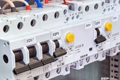
 Thumb rules for surge arrester installation in different earthing systems (photo credit: Dehn)
To evaluate the risk, a formula based on scientific criteria is proposed to engineering and design departments.This formula takes account of the characteristics of the site and the environment:
- Lightning density,
- Type of distribution network,
- Site topography,
- Presence of lightning rods, if any.
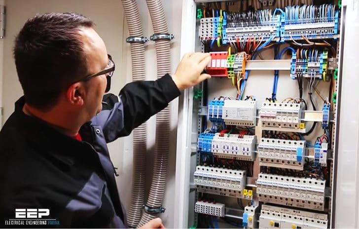
Whatever system is used, if a lightning risk is present, all electrical installations must be fitted with surge arresters (see fig. 1), whose composition may vary according to the type of earthing system.
Figure 1 – Choice of surge protection mode (common or differential) according to the electrical installation earthing system as per NF C 15-443 .
TT system
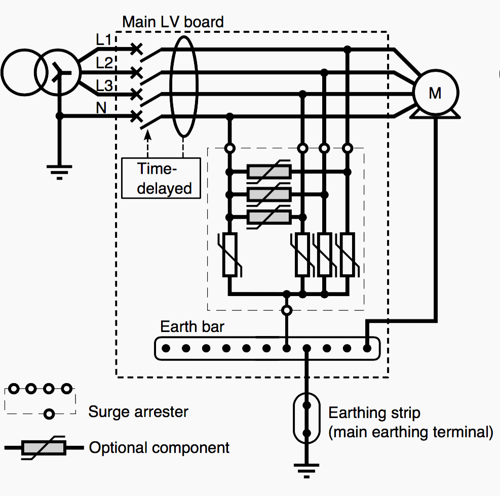
IT system
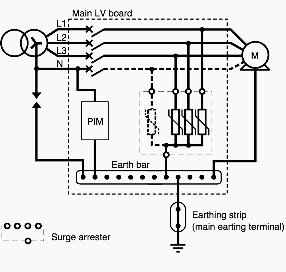
TN-S system
TN-C system
These differences are due to:
- Whether or not differential mode surges are treated,
- The maximum steady state voltage Uc:
- Between live conductors and the earth:
- Uc > 1.5 Un in the TT and TN earthing systems,
- Uc > √3 Un in the IT earthing system;
- Between phases and neutral, Uc > 1.1 Un whatever earthing system is used.
- Between live conductors and the earth:
- Earthing the neutral does not prevent surges from affecting the phase conductors!!
- Surge limiters, use of which is compulsory in the IT earthing system, replace surge arresters for protection against 50 Hz MV surges. As these two devices do not have the same functions, surge arresters continue to be required for lightning surges.
Implementation of surge arresters
A variety of rules are defined (importance of equipotential bonding, staggered or cascading protection devices, use of residual current devices), application of which may sometimes vary according to the installation sector (tertiary and industrial or domestic).
Let’s now discuss about following topics:
- Importance of the equipotential bondings.
- Cascading protection devices
- Cohabitation of residual current devices and surge arresters
Importance of the equipotential bondings
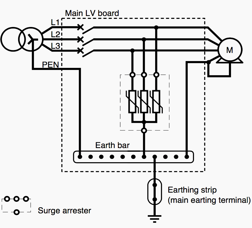
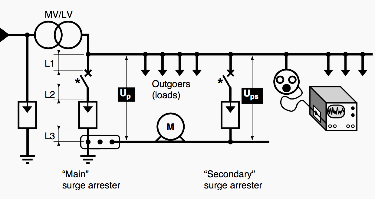
EMC principles state that LV installations must have only one earthing connection for their loads. This connection is close to the origin of the installation, and it is at this level that the “main” surge arrester must be installed (see fig. 2).
Where:
- For increased efficiency of protection, the cable lengths L1+L2+L3 must be reduced when installing a surge arrester.
- Up – protection voltage downstream of the main surge arrester.
- Ups – protection voltage after the secondary surge arrester.
- * – surge arrester disconnection device at end of life (in short-circuit).
Care must be taken to minimize the impedance of its circuit (reduction of its connections to the live conductors and earth, as well as the impedance of the disconnection device).
In this manner, if the surge arrester begins to conduct, the loads are subjected at most to the protection voltage Up equal to the residual voltage of the surge arrester plus the voltage drop in its connections and in the disconnection device. Hence the importance of a properly constructed installation conform to proper practices.
Reminder! One metre of cable has an inductance of 1 μH: application of the formula ∆U = L di/dt with the 8/20 μs wave and a 10 kA current results in a voltage of approximately 1000 volts peak/metre. Hence the importance of minimising surge arrester connecting cable length.
Cascading protection devices
When a high amplitude lightning stroke occurs, the importance of the current flown off by the surge arrester means that protection voltage may exceed the withstand voltage of sensitive devices.
To ensure their effectiveness, these “secondary” surge arresters must be installed more than 10 meters away from the “main” surge arrester. This connection is important as cable impedance performs a decoupling between the two protection levels (as shown in figure 3).
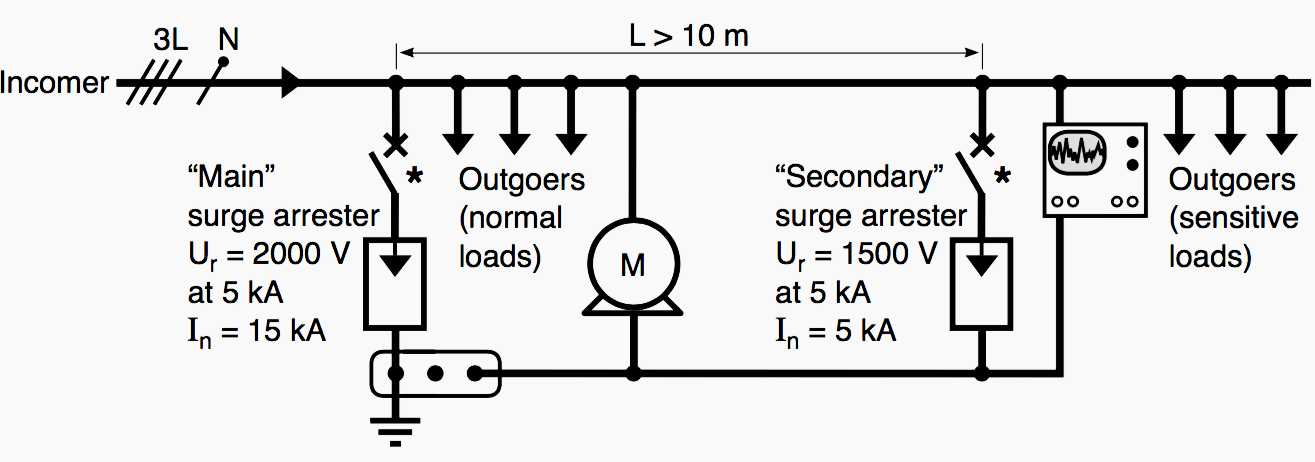
Where:
- This length was defined for surge arresters equipped with varistors
- * – surge arrester disconnection device at end of life (in short-circuit).
It is important to bear in mind that the supply of many electrical devices, and in particular electronic devices, is protected against surge by differential mode varistors. “Cascading” is thus also applied between the surge arrester of the installation responsible for protecting the sensitive device and the latter, and calls for a study of the protection levels.
- Presence of surge arresters on the MV close to those placed on the LV is another case of “cascading” using the differences in arcing voltage of MV and LV surge arresters and the decoupling performed by the MV/LV transformer.
- When electronic devices containing common or differential mode filters are connected near the installation origin, these filters must be able to withstand the protection voltage Up (see fig. 3).
Cohabitation of residual current devices and surge arresters
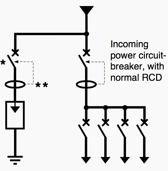
In installations whose origin is equipped with an residual current device (RCD), it is preferable to place the surge arrester upstream of the latter (see fig. 4a).
- * – surge arrester disconnection device at end of life (in short-circuit)
- ** – residual current device for protection of people, in this case associated with the disconnection device.
a) Simplest connection (forbidden in France by EDF)
However, some electrical utilities do not allow intervention at this distribution level. This is the case of LV consumers in France. A time-delayed or selective RCD is then necessary to prevent current flow off via the surge arrester from causing nuisance tripping (see fig. 4b).
b) Recommended connection: also enables discrimination with high sensitivity RCDs placed on the outgoings
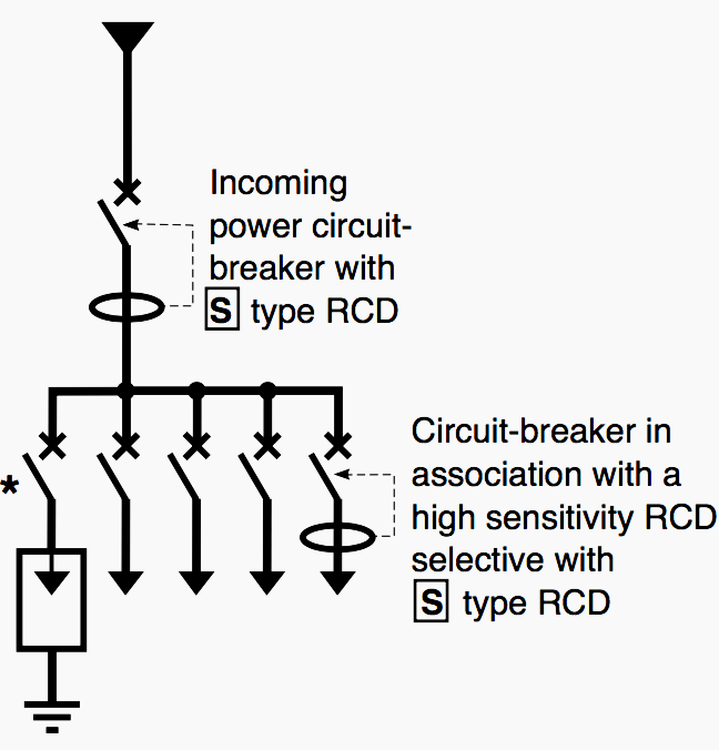
Likewise, if surge arresters have to be installed near high sensitivity RCDs (10 or 30 mA), they must be placed just upstream of them.
To conclude…
In tertiary, industry and the domestic sector, installation of a surge arrester must always comply with the following requirements:
Requirement #1 All surge arresters must be equipped with a disconnection device (de-energised when it is short-circuited): a fuse or a circuit-breaker. This device must be adapted to the surge arrester and its connections (by its rating and tripping or blowing curve) as well as to its installation point (by its breaking capacity).
As a rule, manufacturers specify the characteristics of the device to be provided for each type of surge arrester.
Requirement #2 The connections from the surge arrester to the live conductors and from the surge arrester to the main equipotential bonding must be as short as possible: 50 cm is the maximum value.
Requirement #3 Surge arrester cabling must not create a loop surrounding devices sensitive to electromagnetic phenomena (electronic clocks, programmers, etc.).
Note: Both for initial choice of surge arrester and for its installation requirements, it is vital to consult the manufacturers’ technical documents.
Reference // LV surges and surge arresters LV insulation co-ordination by C. Séraudie (Schneider Electric)
Related electrical guides & articles


Edvard Csanyi
Hi, I'm an electrical engineer, programmer and founder of EEP - Electrical Engineering Portal. I worked twelve years at Schneider Electric in the position of technical support for low- and medium-voltage projects and the design of busbar trunking systems.I'm highly specialized in the design of LV/MV switchgear and low-voltage, high-power busbar trunking (<6300A) in substations, commercial buildings and industry facilities. I'm also a professional in AutoCAD programming.
Profile: Edvard Csanyi

The connections from the surge arrester to the live conductors and from the surge arrester to the main equipotential bonding must be as short as possible: 50 cm is the maximum value.
Practically, how do we reach such values in L.V switchboards .
Is it possible to get some practical examples ?
Thank you
Thank you!
i m cctv engineers, i needmore info how to protect my cctv installation to lightning and surge, i will explain to my students and clients. Thanks and rgds
Agradezco al Portal de Ingeniería Eléctrica por difundir y aportar en nuestro crecimiento intelectual, con la variedad de temas de interés que nos fortalece en conocimiento día a día. Deseándoles sigan adelante con tan valiosa labor y que todos los colegas alrededor del mundo que aprovechamos este medio, aportemos de alguna forma para que el Portal cada día se fortalezca mas.
Inmensamente agradecido por tan valiosa difusión de la información técnica.