
Estimated Study Time: 22 minutes
Time synchronisation
The needs and exact precision of time synchronization in IEC 61850 based digital protection systems have evolved. With new technologies and better distribution methods, most modern intelligent electronic devices (IEDs) include at least one form of time synchronization.
 Critical role of time synchronisation in IEC 61850 based digital protection systems
Many devices offer multiple ways to synchronize device time, providing different or higher-accuracy synchronization. This article discusses some of these time-synchronization needs. Precision time synchronization is gaining popularity in the electric power industry, with a number of new applications promising to improve power system operation.
IEC 61850
The standard IEC 61850 for communication in substations defines a domain specific data model (data and services) supporting all functions implemented within substations.
A specialisation of the IEC 61850-9-2 – known as IEC 61850-9-2 LE – has been created by major suppliers in order to define some of the parameters and facilitate interoperability.
There are two time critical services defined:
- The GOOSE (generic object oriented substation events) service with fast messages (transfer time <4 ms for 50 Hz) is focused on information exchange between IEDs like trips, blockings or releases.
- The SV (sampled values) service is intended mainly for the transmission of synchronised voltage and current samples.
One precondition to implement efficient protection functions is to ensure that the sampled voltage and current values are accurately time synchronised.
According to the required protection functions, the synchronisation is either local, i.e. the devices of one substation have to be synchronised, or global, i.e. the devices of two different substations have to be synchronised.
For IEC 61850 synchronisation is performed by a PPS pulse on a dedicated wire/fiber, but it will be replaced in the future by synchronisation over the Ethernet according to IEEE 1588. This bus allows common solutions for Non-conventional and conventional sensors and actuators.
The functions in any protection or control IEDs using the process bus generally do not see any difference.
Three alternative time synchronisation scenarios for different applications in numerical protection systems are discussed.
- The first synchronises two Merging Units (MUs) directly using a connection between the units.
- The second synchronises the bay device using one MU directly or with a slave MU synchronised by a time master MU.
- The third synchronises a busbar protection scheme using the MU in each bay.
A “Ping-Pong” principle based synchronisation algorithm applied to a decentralised busbar protection scheme and a differential line protection scheme is proposed. The time offset between MUs and the phase difference of the sampled values (SVs) are analysed in detail.
To keep the time shift between MUs as low as possible, drift compensation for the local sampling is introduced.
However, one of the issues of concern is its reliability in case of GPS signal loss (e.g. due to atmospheric disturbances or failure of the GPS antenna for certain reasons) or master clock failure, which would lead to the desynchronisation of the devices inside a substation or between different substations.
Two approaches based on democratic algorithms and prediction techniques are available to improve reliability.
Synchronisation Architecture Scenarios
Developments in network communication technologies are delivering significant benefits for power system protection and control. This includes using microprocessor relays and non-conventional instrument transformers (NCIT) to implement numeric protection.
The analogue signals from instrument transformers were traditionally hardwired to conventional protection relays and IEDs.
However, conventional analogue inputs are now being replaced by an Ethernet message that contains one or more sets of samples derived from a Merging Unit (MU) operating in conjunction with instrument transformers.
The MUs are defined as interface units that accept multiple analogue inputs from CTs and VTs and the binary inputs from open/closed contacts.
The term synchronisation can be misleading in the sense that it suggests a central clock that distributes time information to all bay devices. This may be required for some applications like time tagging of events (1ms).
For example, Furnas Centrais Elétricas S.A, the largest Brazilian utility, has defined and is implementing a centralised and modular timing and frequency distribution system that provides superior reliability, redundancy and remote monitoring functionality. The concept was defined as Site Master Clock (SMC). But it is not a requirement for the sampled analogue values.
The optimised scenarios to meet different requirements for time coherence may be realised by the following approaches:
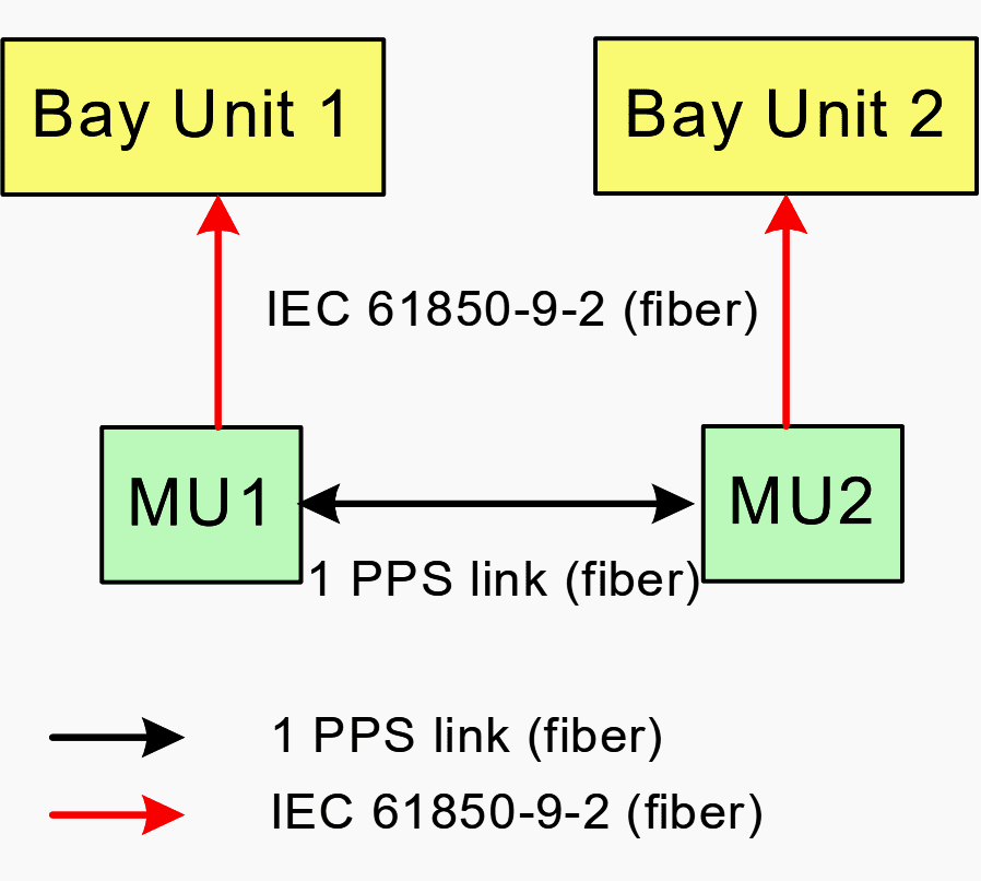
Approach #1
Synchronise two MUs using a direct connection between the MUs as shown in Figure 1. This may be required for parallel line compensation where the synchronisation is between two independent MUs located in two bays.
It may also be required for voltages, when the time information associated with them needs to be distributed by the MU to all the bays requiring this voltage.
Approach #2
Figure 2 shows the scenario to synchronise the bay device from the MU directly or with one slave MU synchronised by another time master MU.
This can be adopted when the bay device has local sampling of the conventional CT and VT signals and these need to be synchronised with the data of the MU or via a technique which time correlates the output to the sampled input data.
Approach #3
Synchronise the busbar protection from the MU in each bay as shown in Figure 3. This allows for re-sampling of the data from all bays to a common time base in the busbar protection.
This will require different topologies for the 1 pulse per second (PPS) that is dependent on whether the protection is centralised or decentralised. It will also support mixed mode with local sampling in the busbar protection.
To realise this, the MU and the protection devices must comply with the following rules:
- The physical MU should contain more than one logical MU. This reduces the need for external synchronisation.
- The MU should be capable of sending and receiving the 1 PPS time synchronisation signal. This removes the need for additional centralised or distributed clocks or time sources.
- Protection and control devices need to be able to receive the 1 PPS signal. This allows for local sampling of conventional CT and VT signals as well as time correlation of the output data to the sampled input data from the MU.
- Busbar protection shall be able to receive the 1 PPS time synchronisation information from each bay and re-sample the data from each bay with the internal clock.
It is worth noting that any loss of time synchronisation between IEDs has to result in a fail safe state that produces a dedicated failure report and continued operation using a local clock designed to loss shall not interfere with tasks which do not need synchronisation.
Related electrical guides & articles


Edvard Csanyi
Hi, I'm an electrical engineer, programmer and founder of EEP - Electrical Engineering Portal. I worked twelve years at Schneider Electric in the position of technical support for low- and medium-voltage projects and the design of busbar trunking systems.I'm highly specialized in the design of LV/MV switchgear and low-voltage, high-power busbar trunking (<6300A) in substations, commercial buildings and industry facilities. I'm also a professional in AutoCAD programming.
Profile: Edvard Csanyi
