
Estimated Study Time: 17 minutes
Time Synchronization
Substation automation is a mission-critical task and electric power utilities must synchronize across large-scale distributed power grid switches in a substation to enable smooth power transfer and maintain power supply integrity.
 Protocols applied for time synchronization in a digital substation automation (photo credit: Siemens)
Precise time synchronization is therefore required to ensure that substation devices have accurate clocks for system control and data acquisition, etc. Time synchronization is especially important for time stamping of sampled values (IEC61850-9-2) of current, and voltage values require accurate clocks inside the merging units.
In substation automation, the following applications require time synchronization:
- Transmission of Ethernet protocols like GOOSE and MMS
- Real-time data acquisition from IEDs, RTUs and MUs
- Real-time process control of equipment like protection relays
- Fault recording for fault and performance analysis
Generally there are two kinds of time synchronization in substation automation: direct time synchronization and synchronization over LAN.
Contents
- Protocols Applied for Time Synchronization
- What is the Benefit of IEEE 1588 v2?
- How does IEEE 1588 PTP Work?
- How to Apply Time Synchronization in Substation Automation
1. Protocols Applied for Time Synchronization
Normally the internal clock within network devices will be synchronized according to a synchronization time server that is connected to a GPS (Global Positioning Satellite) or a redundant satellite. Depending on the substation network application, synchronization time for events and faults can range from sub-microseconds to milliseconds.
Factors effecting time synchronization accuracy depend on the protocol, traffic load, communication media and cable distance of the network.
Dedicated timing systems often use one pulse per second (1-PPS) to provide an accurate timing reference at the start of each second, or the IRIG-B time code for time and date information. GPS (or GNSS) receivers convert the time information received from GNSS into a 1-PPS signal and the IRIG-B time code, which are then used to synchronize all the IEDs in a substation.
An example of a dedicated timing network that operates independent of the substation communication network is shown in Figure 1. When the 1-PPS signal travels from the GPS receiver to the device, a propagation delay is introduced.
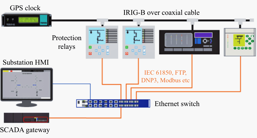
During commissioning, this delay must be measured and compensated.
Substation applications, such as SCADA or disturbance recorders, requiring timing accuracy in the millisecond range, can use a network time protocol (NTP) system operating over an existing Ethernet communication network, as illustrated in Figure 2.
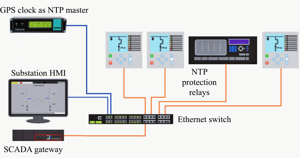
However, most substation applications require timing accuracies in microseconds and consequently NTP is not suitable.
1.1 For Direct Time Synchronization
Traditionally direct time synchronization with the end device can be realized via dedicated wiring with fiber, coax or twisted pair cables to transport the timing signals. Normally only one time server device is required for a time synchronization task. Because the port number in the time server device for direct synchronization is restricted, only a limited number of the devices can be synchronized.
Standard protocols for direct time synchronization in substation automation are GPS, IRIG-B and 1PPS.
1.1.1 GPS
GPS stands for Global Positioning Satellite. The GPS system is highly redundant and can be used for direct time synchronization or as a time source for other time protocols. An antenna for each IED or switch is required for direct time synchronization with a GPS.
The UPS system is capable of delivering timing accuracies of within ten nanoseconds of coordinated universal time (UTC).
1.1.2 IRIG-B
IRIG-B stands for Inter-range instrumentation group time codes B and is the industry standard for GPS time synchronization. IRIG-B can be applied in a substation for power quality and system stability monitoring, sequence of events recording and accurate time stamping for revenue billing (1 ms).
IRIG-B needs an external time source. The accuracy of time sampled values depends on availability and quality of time synchronization can be in the microsecond range (typ. 100 ps).
1.1.3 1PPS
1PPS stands for one pulse per second. It is a high-precision time pulse from precision clocks like a GPS receiver that very precisely indicates the start of a second. 1PPS is sent to every user over separate lines and entails an enormous additional wiring effort.
The accuracy of time synchronization of 1 PPS can be in the micro-second range (typ. 1 ps).
1.2 For Time Synchronization over LAN
Time Synchronization over a LAN (Local Area Networks) synchronizes devices via an Ethernet network and can enlarge the number of devices driven through one Ethernet cable. It reduces the cabling infrastructure and cost by transporting all time synchronization information together with data communications over the same Ethernet communication medium.
1.2.1 SNTP
SNTP stands for Simple Network Time Protocol. It is basically NTP but lacks some internal algorithms that are not needed for all types of servers. It is widely distributed in LANs or on the Internet. SNTP allows accuracy of time synchronization into the millisecond range (typical 1-10 ms).
SNTP is suitable for a station bus but does not achieve the accuracy required by a process bus with GOOSE and SV messages.
1.2.3 IEEE 1588 PTP
PTP stands for Precision Time Protocol and is a future-proof standard Ethernet protocol described in the standards IEEE 1588 and IEC61588 for time synchronization.
IEEE 1588 has two versions and they are not directly compatible. IEEE 1588 v2 is required mostly for IEC61850-9-2 Process Buses or IEEE C37.118-2005 Synchrophasors in sub-station automation and can be converted to IRIG- B.
Distributed clocks in end devices can be synchronized with IEEE 1588 v2 in the sub-microsecond range (type 30-50 ns).
2. What is the Benefit of IEEE 1588 v2?
IEEE 1588 is used for time critical applications such as Substation automation and offers many benefits for utility vendors:
High Availability Solutions
IEEE 1588 v2 use Best Master Clock Selection Algorithm (BMC). The master clock in a substation can receive time synchronization messages from other potential master clocks. All clocks can operate using the same information and therefore arrive at consistent results. Fast resynchronization can be achieved when system changes occur.
At the same time, IEEE 1588 v2 prevents error accumulation in cascaded topologies, supports fault tolerance and enhances the flexibility of the system.
Low Cost Solutions
IEEE 1588 v2 can use an existing Ethernet network and reduce cabling costs. Its unicast message has shorter frame sizes in order to reduce the bandwidth consumed by the network traffic messaging and requires minimum processor performance.
It is easy to implement in IEDs, multicast Ethernet and other multicast capable networks with low cost and simple maintenance.
High Precision Solution
IEEE 1588 v2 synchronizes clocks with differing precision and resolution. It achieves network clock synchronization accuracy in the sub-microsecond range.
3. How does IEEE 1588 PTP Work?
IEEE 1588 PTP has two versions, PTPv1 (IEEE 1588-2002) supports ordinary clock (OC) and boundary clock (BC) mechanisms; PTPv2 (IEEE 1588-2008) supports ordinary clock (0C), boundary clock (BC) and transparent clock (TC) mechanisms.
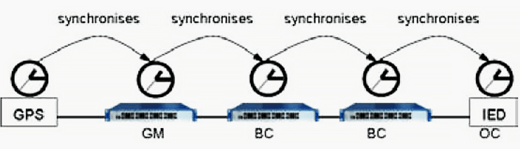
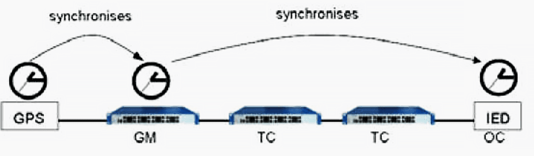
In version one for boundary clock mechanisms, a radio clock or a GPS receiver controls a ground master clock (GM). The ground master clock determines the time base for the system and synchronizes the respective slave clock (BC in the transmission switch or OC in the end device) directly connected to it in each step.
In the slave clock, one port serves as a PTP slave port to an upstream master clock, and the other ports serve as PTP clock masters to downstream PTP clocks.
At first, the time difference between the master and the slave is corrected (offset). Then the delay time between slave and master is measured by delay request and delay response. In the end, the time in the slave or end device is synchronized according to delay time and offset.
In version two for transparent clock mechanisms, transparent clocks correct the “residence time” of the network device like an Ethernet Switch.
The residence time is the time delay incurred by a packet passing through the Ethernet switch and can be calculated by the time stamp between egress and ingress.
This residence time is accumulated in a correction field to realize time synchronization.
Since transparent clocks are stateless they have no impact on the reconfiguration time of ring topology networks for example. Each switch in the path appears to be a “wire” which does not skew the time calculation for packets passing through them.
This avoids the accumulation of jitter and thus reduced accuracy when using many cascaded switches.
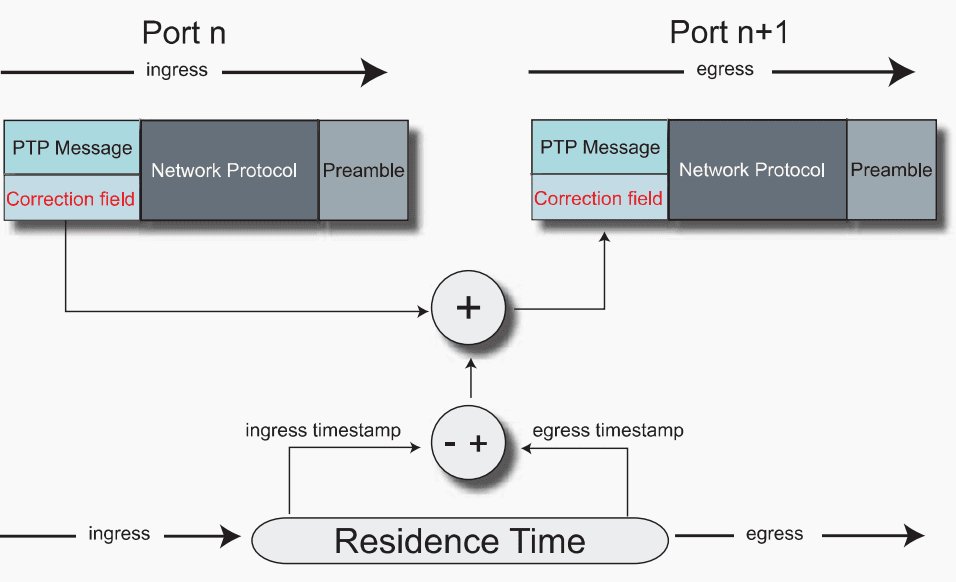
The IEEE 1588-2008 standard supports two types of transparent clocks, namely: End-to-End (E2E) and Peer-to-Peer (P2P).
- End-to-End TCs only measure the time taken for a PTP event message (those that get time stamped) to transit the bridge and provide this information to the receiving clocks in the correction field.
- Peer-to-Peer TCs use the peer delay mechanism and measure the port-to-port propagation delay time between two directly connected ports sharing the same communication technology. The peer delay mechanism is independent of the state of a port (master or slave). It operates separately in both directions of the link.
4. How to Apply Time Synchronization in Substation Automation
Time synchronization for a station bus and a process bus has different requirements. Figure 6 shows one example of how to realize time synchronization with different time protocols in substation automation. As shown in the figure, precise time is provided by a GPS to a time server unit as a precise time source for communication devices like switches or IEDs.
Normally a redundant time source from another time satellite can be applied to enhance system reliability.
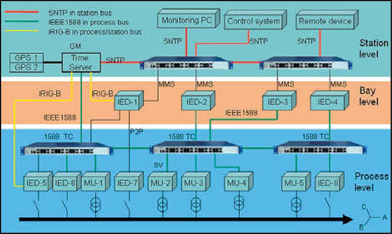
Star topology is very common for time synchronization in a station bus and a process bus. Normally time synchronizations for IEDs at bay and process level are implemented separately. However, a common precise time source can be applied.
Because there are no IP packets in a process bus, transmission protocol IEEE 802.3 is used for PTP messages. IRIG-B and 1PPS require separate cable and synchronize the IED5(e.g. IED-1 and IED-5) at bay and process level.
In order to achieve high availability of time synchronization, some point-to-point communication (e.g. IED-1 to IED-7) between IEDs and MUs can be applied without any communication switch.
As the future-proof time synchronization protocol, IEEE 1588 improves the reliability of the substation network.
References:
- Time Synchronization for Transmission Substations Using GPS and IEEE 1588 by Peter A Crossley, Member, IEEE, Hao Guo, Student Member, IEEE, and Zhao Ma, Senior Member, CSEE
- Hirschmann, White Paper – Data communication in substation communication (SAS)
- IEC 61850 Communication Networks and Systems in Substations, IEC standard in ten main parts, 2002
- Hirschmann, White Paper Precision Clock Synchronization – The Standard IEEE 1588. Rev. 2.01 Andreas Dreher, Dirk Mohl, Markus Seehofer
- IEC 61850-90-4 Technical report: Network Engineering Guidelines, 2012
- Hirschmann Service and Support
- Solving electrical substation timing problems – A white paper on the use of the Precision Time Protocol for substation protection and control systems by Dr David Ingram and Brian Smellie (TEKRON)
Related electrical guides & articles


Edvard Csanyi
Hi, I'm an electrical engineer, programmer and founder of EEP - Electrical Engineering Portal. I worked twelve years at Schneider Electric in the position of technical support for low- and medium-voltage projects and the design of busbar trunking systems.I'm highly specialized in the design of LV/MV switchgear and low-voltage, high-power busbar trunking (<6300A) in substations, commercial buildings and industry facilities. I'm also a professional in AutoCAD programming.
Profile: Edvard Csanyi

thank you a lot .
No need for terrorism can someone shut off all the brain readers ???
This is very Useful to learn time synchronization better. great work and happy
Hi Edvard :
i`m wheely grateful for your great web site & your contribution in giving a very useful post that providing a basic knowledge for undertraining engineers , my friend we have in iraq a 400kv super grid substation , it has a SCS system type Alstom ds Agile , the hardware network is completed , but the data base of substation not installed yet, can you start posting about basic of making a data base for such control system ,also we have in other substation SCS system type microscada Siemens sicam pas have similar principles, we need to know how to prepare data base for such substation , what the required resources , what the prices of software ..etc. .
regards
regarding the sicam pas and sicam scc ,i can support you on the iraq subsation ,let me know the architecture ,then we can discuss .