
Estimated Study Time: 10 minutes
Wiring tips | Connections & routing
Wiring industrial control panels is a complex process and it needs a number of carefully planned and performed details. However, there are dozen of tips and advices on how to do this and that, but this technical article will limit to wire connections and routing inside of control panels.
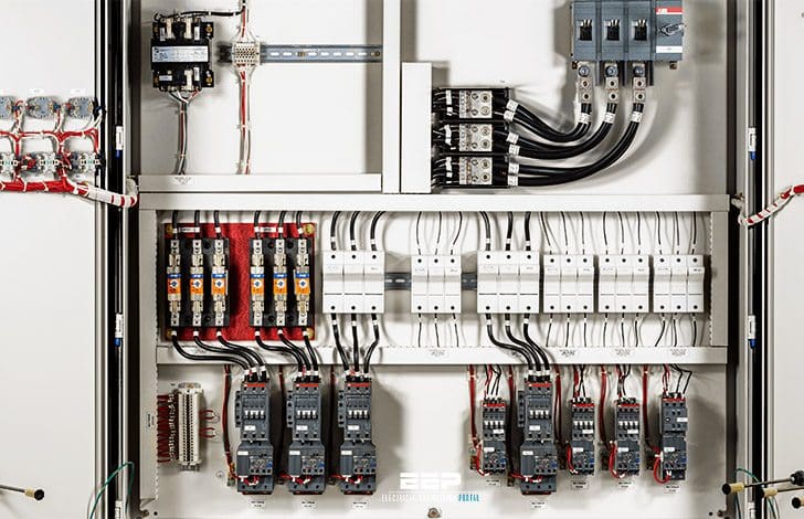 Connections and routing tips for wiring industrial control panel (photo credit: powerindustrialcontrols.com)
Let’s discuss now about tips and advices you should take into account when wiring the control panel:
1. General tips
These are some general points that should be taken into account when wiring the control panel.
#1
Connections should be secured against accidental loosening. Correctly tighten terminal screws and where a connecting plug is fitted, use the clamps or screws provided to secure it to its mating socket.
#2
Particular attention in this respect should be taken with the protective bonding circuit, for example by using star washers and a lock nut where necessary.
#3
Two or more conductors may only be connected to a terminal that is designed for the purpose. The majority of connecting blocks will only take one or two conductors. Don’t force in any more.
#4
Add an additional terminal and connect it to the other by a link laid in the cable trucking to gain an extra connection point.
#5
Soldered connections should be made only to terminals suitable for that purpose. Transformers may be fitted with turret tags suitable for soldering and printed circuit board assemblies may have solder pins.
#6
Terminals and terminal blocks should be clearly marked and identified to correspond to the markings in the drawings.
Ensure that identification tags and cable markers are legible, marked with a permanent ink and suitable for the environment where the panel is to be used. They should also correspond with those shown in the machine drawings and instruction or service documentation.
#7
A means of retaining conductor strands should be provided where terminals are not equipped with this facility, for example by crimping on bootlace ferrules. Do not use solder.
#8
The terminations of shielded or screened conductors should be terminated so that the screen cannot fray. If the screen is to be connected then make it off in the same way as for coaxial cable with a soldered pigtail and a sleeve.
If it is not to be connected then trim it back as far as possible and cover it with a sleeve.
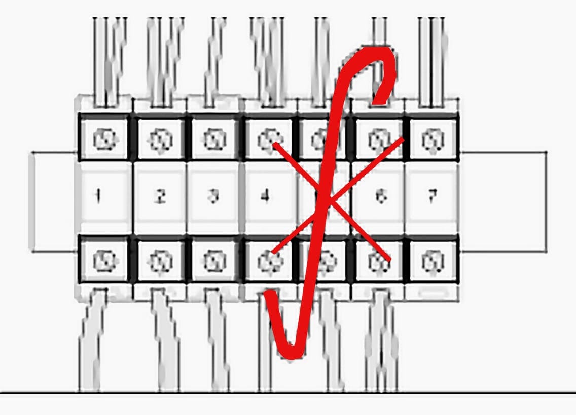
#9
Terminal blocks should be mounted and wired so that the internal and external wiring does not cross over the terminals.
#10
Flexible conduits and cables should be installed in such a way that liquids can drain away from fittings and terminations.
2. Conductor and cable runs
#1
Conductors and cables should run from terminal to terminal without any intervening joins. This refers to making a joint in the middle of a wire or cable. If it is necessary for any reason then use a suitable connector or terminal block. Don’t use a twisted and soldered joint.
Extra length should be left at connectors where the cable or cable assembly needs to be disconnected during maintenance or servicing.
#2
Multicore cable terminations should be adequately supported to avoid undue strain on the conductor terminations.
#3
The protective conductor should as far as is possible be routed close to the associated live conductors to avoid undue loop resistance.
3. Conductors of different circuits
This refers to wires and cables that are in the same enclosure but are connected to different parts of the system, for example power wiring that could be carrying high currents at 415 volts.
Signal wires that may be connected to sensors and to the input terminals of a programmable controller and therefore carrying only low currents at 5 to 24 volts.
When the current is switched on or off, the electro-magnetic field increases and decreases, rapidly causing, in effect, a radio signal. The effect is similar to the crackle that can sometimes be heard on the radio or television when something like a fridge switches on and off. This radiated signal can be picked up by the other wires in the system and cause interference to the normal working voltages in the system.
This is known as Electromagnetic Interference or EMI. The Electro-magnetic Compatibility (EMC) Regulations require that these effects are minimized.
In many cases, it is the layout of the wiring that is critical to avoid interference and this will have been worked out by the designer. This aspect of wiring concerns the EMC regulations. The layout of such wiring should be specified by the designer and must be adhered to.
Where the circuits work at different voltages, the conductors must be separated by suitable barriers or all the wires insulated for the highest voltage to which any conductor may be subjected.
A lamp inside an enclosure provided for use during maintenance is an example of such a circuit. The control panel may be isolated but the lamp will require power so that the engineer can see while working on it.
Reference // Industrial Control Wiring Guide by Bob Mercer
Related electrical guides & articles


Edvard Csanyi
Hi, I'm an electrical engineer, programmer and founder of EEP - Electrical Engineering Portal. I worked twelve years at Schneider Electric in the position of technical support for low- and medium-voltage projects and the design of busbar trunking systems.I'm highly specialized in the design of LV/MV switchgear and low-voltage, high-power busbar trunking (<6300A) in substations, commercial buildings and industry facilities. I'm also a professional in AutoCAD programming.
Profile: Edvard Csanyi

I would love to acquire more knowledge on this…… I am a passionate upcoming engineer
Sir provide more article and video about electrical panel.